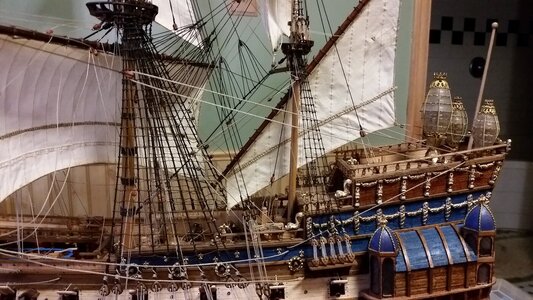
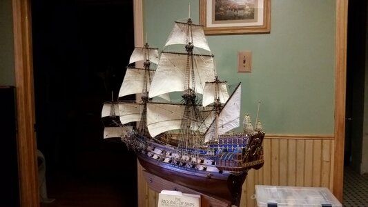
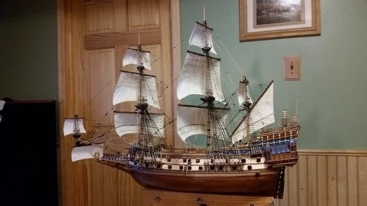
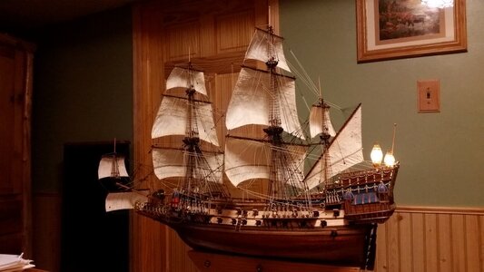
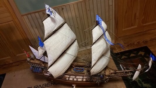
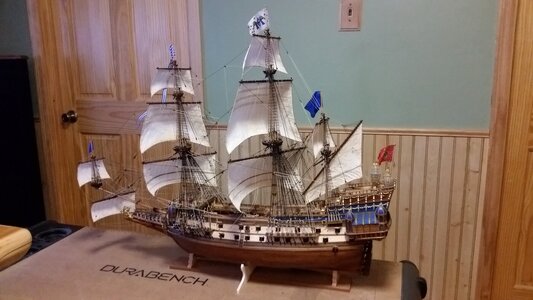
La Couronne Corel/scratch 1:100 First build [COMPLETED BUILD]

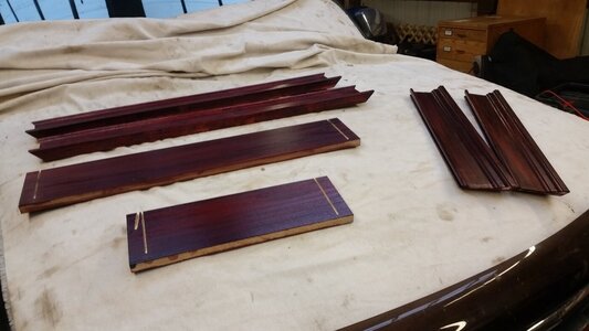
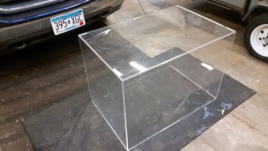
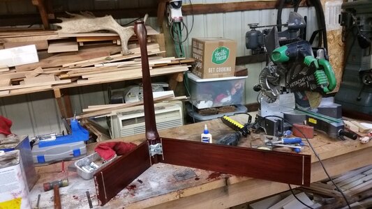
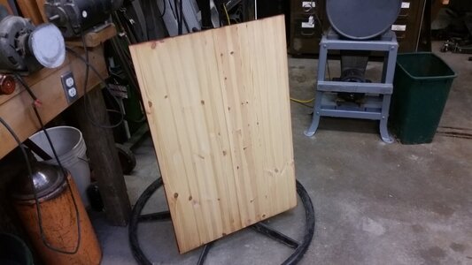
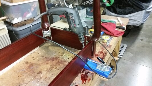
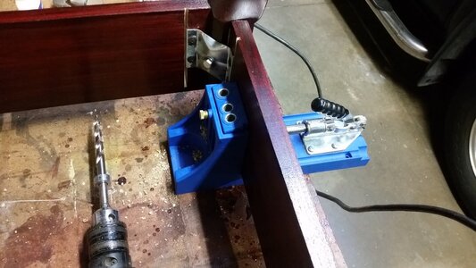
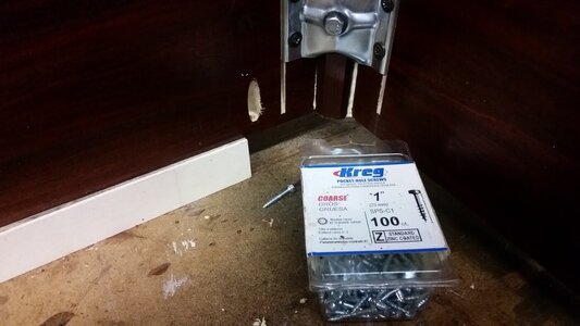
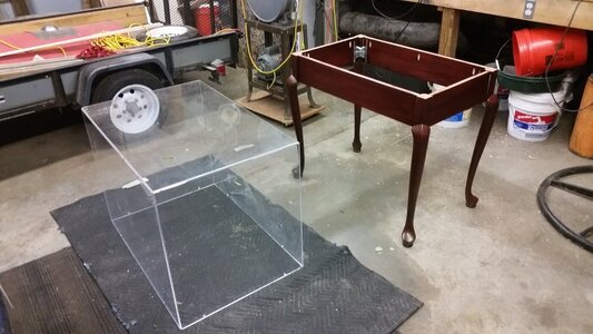
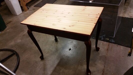
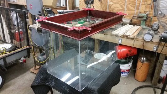
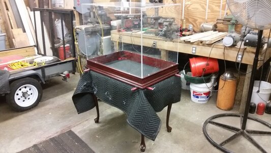
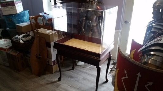
Work continues on the display table I am quickly assembling out of used and new wood, with the used Plexiglas enclosure. Once the riser base on the bottom of the Plexiglass is dry, the table top will be prepared with mounts for the model and a hole for the electrical cord to pass through for it's internal lights. This is by no means a professional piece of furniture, having a simple stain and two coatings of shellac, with one coat of polyurethane on the raw knotty pine surface, but it's not bad for three afternoon's work. I got the legs and hardware donated from a a friend's cheap Chinese made desk he was scrapping. I'll spend the $700.00 for a better display case later for the next ship. Yeah.. one of the pieces of wood fell on the moving saw blade... :rolleyes:

1312 Begin Assembling Display Case.jpg

1313 Used Plexiglass Enclosure.jpg

1314 Assembling Table Base.jpg

1314 Table Top.jpg

1315 Drilling Screw Pilot Holes.jpg

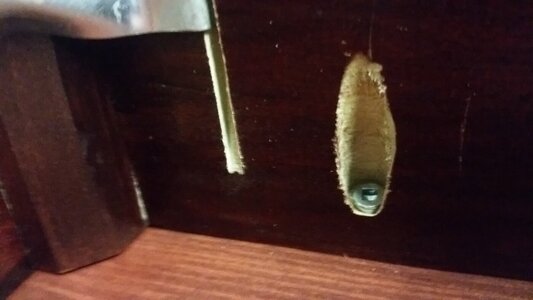
1315 Use Kreg Tool for Screwed Joints.jpg

1316 Kreg Screws for Joints.jpg

1317 Table Base Assembled.jpg

1318 Screw Base to Table Topt.jpg

1319 Table Complete.jpg

1320 Assemble Risers with PVA Glue to Raise Plexiglas 10 cm.jpg

1321 Allow Corner Joints to Dry.jpg
 
Lots of work was done today. After twelve hours, all the running rigging was completed. All that is left now is making and adding the flags and pennant, making the base to hold the ship, and running the electrical cord through the table top and finish assembling the display case. ALMOST DONE.

So, here are the final steps for the running rigging...

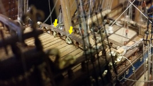
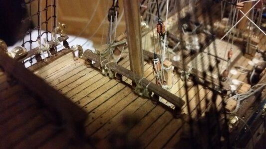
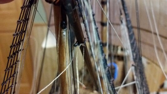
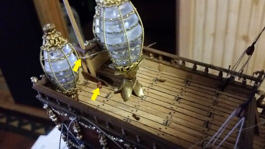
The lateen leechlines were belayed to the rail just behind the mizzen mast. It seemed a better location that belaying them to the the bulwark rails.
1322 Lateen Leech Line Belaying Points.jpg

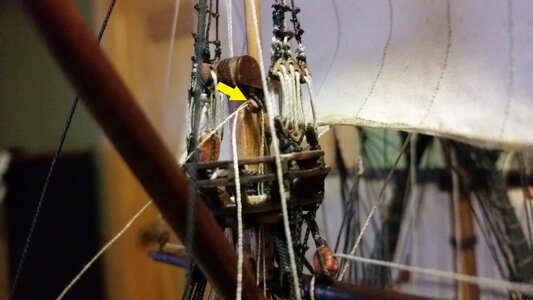
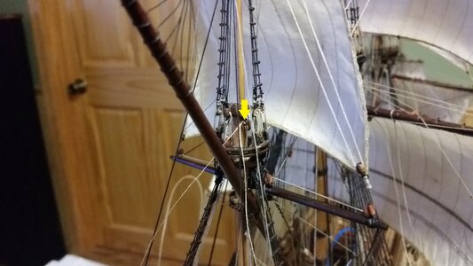
The leech lines are then run up to a double block attached to the mizzen masthead.
1323 Double Block for Lateen Leech Lines.jpg

Here is a better view of that double block,
1324 Double Block for Lateen Leech Lines.jpg

The brail lines are belayed to the same rail, just outboard of the leech lines.
1325 Belaying Points for Brail Lines.jpg

The brail lines are run up through single blocks on the lateen yard just a bit forward of the mast.
1326 Brail Line Blocks on Lateen Yard.jpg

With the leech and brail lines hanging loose, I shifted to preparing to rig the lateen sheet line. Since the knee on the taffrail on this model does not extend up the taffrail vertically, I attached the sheet to the flagstaff support timber. A block for the sheet tackle was attached to the knee at an eyelet with a hook stropped to the block.
1327 Lateen Sheet Line Tied to Stern Timber and Block.jpg

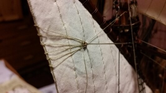
Moving back to the lateen sail, sail is bent to the yard with gaskets. This was a challenge since there was no little room for fingers or tools. The leech lines were tied to the martnet deadeyes on both sides of the sail. A needle stuck through the deadeye into the sail holds the deadeye in place to make tying easier.
1328 Hold Martnets with Needle While Tying Leechline to Deadeye.jpg

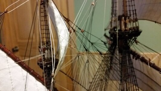
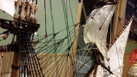
Things got faster at this point. The tack line for the lateen was simply run to the center of the rail beneath the front clew, and included a rope coil on the rail like all the other lines tied to rails. The sheet line was run from the stern timber to a block on the rear clew, back to the block on the knee, then tied to one of two cleats I installed on the poop deck, in this case, the starboard cleat. The temporary brace lines for the topsail yard and crojack were cut free, and the braces for both rigged. for both yards, the braces start at belaying pins adjacent to the kevel in the bulwark, the run up through blocks tied to the aftermost main shrouds, then to the brace pennants and back to the aftermost main shrouds where they end.
1329 Leechlines With Martnets and Brail Lines Rigged on Both Sides.jpg

Finally, the main braces are made taut and the ends tied to the eyelets and rings on the hull near the stern and secured.
1330 Lateen Tack and Sheet Lines, Topsail and Crojack Braces, and Main Course Braces  Rigged.jpg

Now I can sit back and look at it for a while.
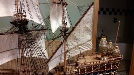
1331 Runnig Rigging Complete.jpg

1332 Progress So Far 52.jpg

Let's see if the lights still work...
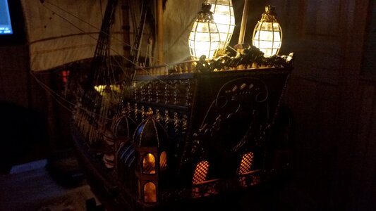
1333 Stern and Deck Lighting on.jpg

1334 Stern With Lighting on.jpg

Yup.
 
Last edited:
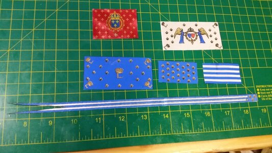
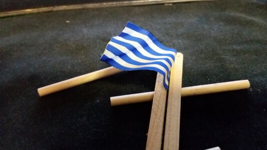
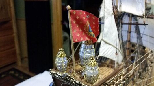
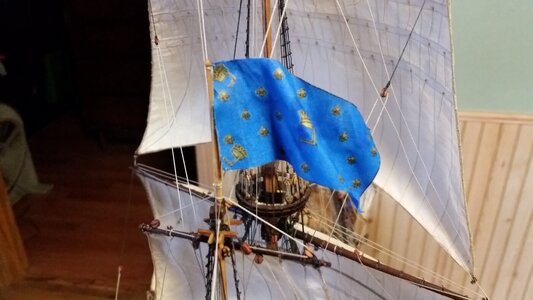
Most of the Corel supplied flags have indistinct image lines and faded color, so I purchased a set of French flags from Amati for the ship St. Louis, which are the same flags that should be on La Couronne. The are a bit larger, but not overly much. The Corel supplied red flag for the flagstaff on the stern was retained, however, because the Amati one was too large, and would foul on the stern lanterns. Prior to cutting them out of the cloth, CA glue was carefully applied around each flag and allowed to seep toward each flag image without intruding into the flag. This prevents the edged from fraying. Then the flags were cut out. There is enough CA glue in the edges to hold the fibers together without lots of discoloration. There are probably better ways of doing this, but that's what I did this time using what I had.

1335 Cut Out Amati Flags and Corel Flag (Red).jpg
 
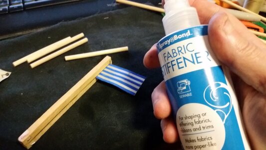
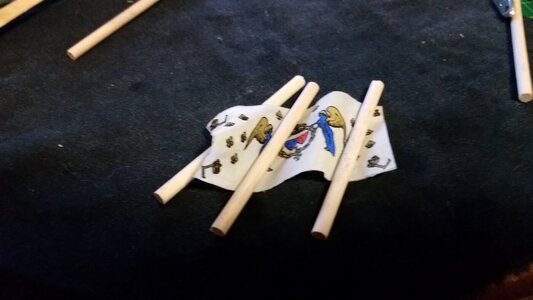
The flags were shaped, starched, and rigged to the flag staves. Making and installing rope hanks of belaying pins is the next and last step. Flags were clamped into the same clamp I used to guide the tying of the ratlines on the shrouds. The flags are soaked through with fabric stiffener, then shaped over several dowels. While holding the cluster of dowels and wet flag in one hand, a hot air gun was used to dry the flag in about two minutes, taking care not to burn your fingers.

Each flag is rigged with a long loop of thin thread. The thread is loop and tied to a belaying pin or rail (or timber for the stern flag) and the two ends are run up to the flag staff. One end is set aside while the other is passed through the bottom corner with a needle and a double overhand knot is made loosely so the delicate flag fabric is not crushed or torn. The fabric of the flag should held by a loose loop of thread with this knot, not tight, or the fabric will tear. This knot is also used to set the height and location of the flag on the flagstaff, such that the line running back down to the belaying point is taut, so make fit the flag and judge its position before cinching up the second overhand pass of the knot. There should be about 6" or more of length of thread on the end after the knot is made. The knot is secured with a very small about of CA applied with a dental pick.

Next, use a needle to pass the end of the thread through the flag's upper corner and tie another double knot to form a loose loop of thread which holds this corner of the flag. Before setting the knot, make sure the flag is very slightly more loose that the thread between the two knots. When under tension, this thread should bear the load, not the hoist edge of the flag, just like a real flag. (I used to be in the Color Guard back in the Academy, so I know a bit about flags. Raising a Ensign #1, a 19'x38' American flag up 120' of unguyed flag pole teaches you certain things). Drawing the flag up to make the entire line taut, tie it to the top of the flag staff just below the ball, and add a bit of CA to hold it there, but do not cut off the excess thread. Now take the second line that comes from the same belaying point, and tie it to the end of the first thread, joining the two just below the ball, and thus simulating both lines coming down from the truck below the ball. Secure the knot with CA glue and trim the two ends off.

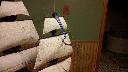
For the pennant, a painted copper nail was used for the spreader at the hoist edge of the pennant, and thread was used to tie the pennant to the spreader, and to the foremast below the foremast flag. Since the streamer could not be suspended in the air, it was positioned in a half-blown draping shape and glued in two very small spots to the fore topgallant starboard bowline. Being suspended by the rigging gives some illusion that is suspended by wind, and appears with a nice, artistic effect.

1336 Clamp Flag and Soak With Fabric Stiffener.jpg

1337 Fold Flag Over Dowels and Dry With Hot Air Gun.jpg


1338 Flag Shaping Finished .jpg

1339 Rig Stern Flag.jpg

1340 Rig Mizzen Flag.jpg

1341 Attach Pennant and Glue to Rigging With Small Spots of Glue.jpg

1342 Adjust Flags To Direction of Wind.jpg

1343 Progress So Far 53.jpg
 
Last edited:
I almost forgot to rig the mizzen topsail bowlines. So, here they are. The bowlines lead from the bridals on the leeches of the sail to single blocks on the after most main shroud, between the level of the crojack and the futtock staves of the mainmast in height. Then they go down to belaying pins on the bulwarks, which is a guess on my part, but those belaying points make sense since they will not interfere with the lateen sail or cross over the grates, which need to be clear in order to move items in or out of the hold.

1344 Stbd Mizzen Topsail Bowlines Rigged.jpg

1345 Port Mizzen Topsail Bowlines Rigged.jpg
 
Last edited:
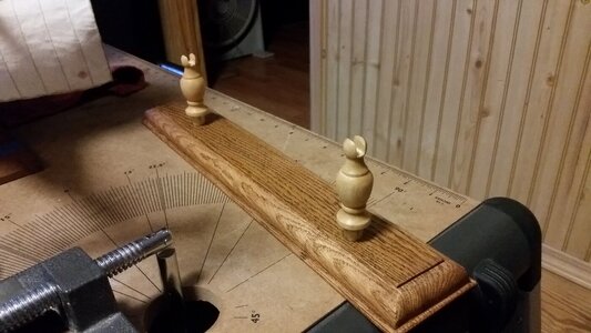
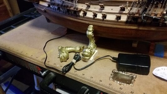
Thanks Janos, Charles QC, and the rest of you guys. I'm still playing with different ideas as to how to support the ship, but here's what I came up with. I made a wood base from some dirty scrap oak I found in the shop, and bought a couple wooden pedestals at Menards, a home improvement store. The pedestals are shown sitting on top of the oak base. Because they will not strongly support the ship from leaning over onto its side, I plan on putting one of these cheap plastic Chinese fish stents under the hull on each side. I painted them gold after filing the mold flash off and will cut the tails at the correct angle to the hull surface, and add pads to them. The fish shown below is in the approximate location, except that the fish will be much lower and its tail will be under the hull. That will provide for four points of support. I still need to come up with name plates. The Corel one is a gold covered metal casting that is a bit small for the ship's name. If any of you guys make nameplates with fancy lettering and graphics, such as the blue/gold French coat of arms, let me know. Looking for ideas here.

1347 Idea For Base.jpg

1348 Plastic Dolphins Will Support Each Side.jpg
 
Hello everyone!

Like my father before me, I sailed merchant ships as an Engineering Officer, and have always loved square riggers. After eight years living aboard ship, seawater still flows in my veins twenty-five years later. I built several plastic ones as a boy, and now am returning to the hobby decades later, this time with experience in medieval weapon and armour smithing, carpentry, machining and other trade skills. A decision had to be made as to which era of sailing ship to choose.

The 17th century royal great ships peaked my interest because of their embellishment and style, set apart from the advanced, refined warships of the Lord Admiral Nelson's time. So, the first ship, what I consider my training vessel, is La Couronne c. 1636. It's an ambitious ship for a novice such as myself. EJ's La Couronne build on the Nautical Research Guild was an inspiration, and his build log serves me well as a guide, since plans alone are not sufficient for a first time project. I also purchased Deagostini's Sovereign of the Seas, all packages, and am saving that for building closer to retirement in 10-13 years. The challenge of the small scale of 1:100 of La Couronne is rather high, trying to include the level of detail I desire, plus the addition of either full or battle sails. Silkspan is the material that is planned to used for the sails. I hope I don't tear them to ribbons in the process! A ship isn't complete without sails, no matter that they block some of the view of the deck equipment.

La Couronne so far is about 50% done, with the additions of: properly scaled 18 pound, 9 pound, and 6 pound bronze cannons, use of Falkonet small 2mm blocks instead of the monster blocks supplied with the kit, cannon carriages of walnut instead of dummy barrels, internal circuit board with flickering candle effect LED lights for upper gun deck, stern and side galleries and turrets, and of course, stern lanterns. Below is a link to 264 photos (and growing) of the progress of the build, every step of the way, all numbered to allow one to see the progress in order.

I would treasure your comments and suggestions on how to steer this build in the direction of perfection, or questions as how features of this model were chosen and performed. All of you who have posted your own builds have unwittingly educated me in this build every step of the way.

Best wishes!

Kurt Suleski
DARIVS ARCHITECTVS (Latin for Darius the Engineer)

La Couronne Build Photos

264-Test-Fit-Towers.jpg
Hallo Kurt,
we wish you all the BEST and a HAPPY BIRTHDAY
Birthday-Cake
 
Back
Top