-

Win a Free Custom Engraved Brass Coin!!!
As a way to introduce our brass coins to the community, we will raffle off a free coin during the month of August. Follow link ABOVE for instructions for entering.
-

PRE-ORDER SHIPS IN SCALE TODAY!
The beloved Ships in Scale Magazine is back and charting a new course for 2026!
Discover new skills, new techniques, and new inspirations in every issue.
NOTE THAT OUR FIRST ISSUE WILL BE JAN/FEB 2026
You are using an out of date browser. It may not display this or other websites correctly.
You should upgrade or use an alternative browser.
You should upgrade or use an alternative browser.
Le Commerce de Marseille 1788 - 1801 scale 1:48 from Gerard Delacroix
It looks nice but ‘complex’ Ronald.Another update..... I have now added a part of the stern, see photos....
View attachment 334823
View attachment 334822
View attachment 334821
View attachment 334820
Regards, Peter
Unfortunately, it no longer fits like a glove...
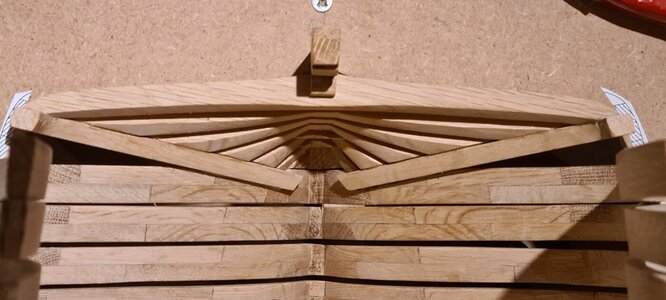
When placing the horizontal parts, the first part did not fit properly, see below:
It seems that the drawing is not correct, moving it to the back didn't seem an option either because I had made the parts exactly according to the drawing, and the shape of the beam seemed to be exactly right with the 'rabbit', the notch where the planks come in to fall. I thought, mistake, and made another...
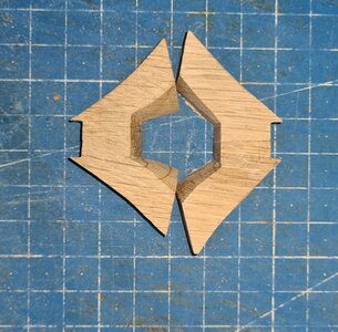
On the left the existing one, on the right the 'corrected'...
Placed the corrected one, and the other beams also placed and glued.
Result:
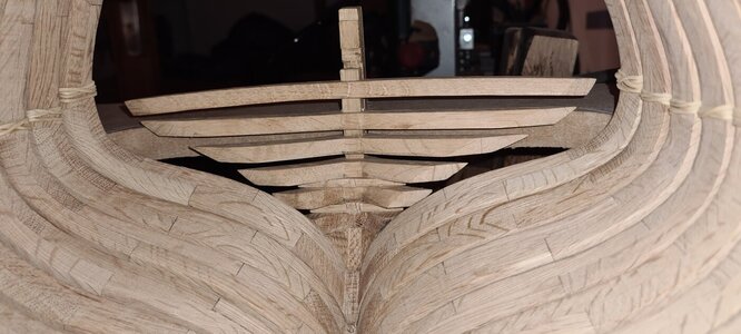
I thought, solved.... Then placed the vertical part:
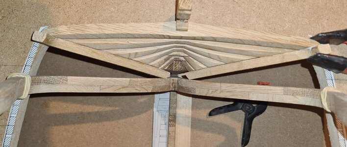
And here I found out that the first beam was correct, it doesn't fit well on the vertical beam, but I thought: I'm not going to remove everything for that, I can shape the outside well, only the inside is not completely correct. I can fix this later with shims, or put planks over it. Not worth demolishing everything again. This was mistake number 2. What I didn't notice, or at least didn't understand the consequences of this, was that the vertical beam stood too far forward....
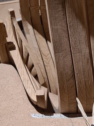
It makes a difference of 3 to 4 mm. However, this photo also shows that the top beam is correctly placed on the keel when you look at the notch in it and the shape of the beam....
I glued everything together, it was well put together, and I thought that demolishing and reassembling would not lead to a better result (I told myself that).
I made the next mistake, the fitting of the last frame:

But now I'm faced with a dilemma.... 3 to 4 mm is quite a lot looking at what is yet to come. When I want to fix this, assuming that everything goes well, I have to renew everything up to the replacement of the last frame. I don't know exactly where I went wrong though, looking at:
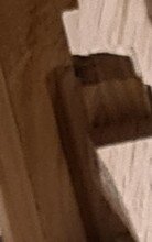
It seems that placing everything back is also causing problems.....
When placing the horizontal parts, the first part did not fit properly, see below:

It seems that the drawing is not correct, moving it to the back didn't seem an option either because I had made the parts exactly according to the drawing, and the shape of the beam seemed to be exactly right with the 'rabbit', the notch where the planks come in to fall. I thought, mistake, and made another...

On the left the existing one, on the right the 'corrected'...
Placed the corrected one, and the other beams also placed and glued.
Result:

I thought, solved.... Then placed the vertical part:

And here I found out that the first beam was correct, it doesn't fit well on the vertical beam, but I thought: I'm not going to remove everything for that, I can shape the outside well, only the inside is not completely correct. I can fix this later with shims, or put planks over it. Not worth demolishing everything again. This was mistake number 2. What I didn't notice, or at least didn't understand the consequences of this, was that the vertical beam stood too far forward....

It makes a difference of 3 to 4 mm. However, this photo also shows that the top beam is correctly placed on the keel when you look at the notch in it and the shape of the beam....
I glued everything together, it was well put together, and I thought that demolishing and reassembling would not lead to a better result (I told myself that).
I made the next mistake, the fitting of the last frame:

But now I'm faced with a dilemma.... 3 to 4 mm is quite a lot looking at what is yet to come. When I want to fix this, assuming that everything goes well, I have to renew everything up to the replacement of the last frame. I don't know exactly where I went wrong though, looking at:

It seems that placing everything back is also causing problems.....
Yes Peter, it is.... I am in doubt what to do with this.... I think I can correct a lot, and a lot will not even be visible later on, but I am not sure of the consequences when I do not correct this difference...It looks nice but ‘complex’ Ronald.
Regards, Peter
Unfortunately, it no longer fits like a glove...
When placing the horizontal parts, the first part did not fit properly, see below:View attachment 334824
It seems that the drawing is not correct, moving it to the back didn't seem an option either because I had made the parts exactly according to the drawing, and the shape of the beam seemed to be exactly right with the 'rabbit', the notch where the planks come in to fall. I thought, mistake, and made another...
View attachment 334825
On the left the existing one, on the right the 'corrected'...
Placed the corrected one, and the other beams also placed and glued.
Result:
View attachment 334826
I thought, solved.... Then placed the vertical part:
View attachment 334827
And here I found out that the first beam was correct, it doesn't fit well on the vertical beam, but I thought: I'm not going to remove everything for that, I can shape the outside well, only the inside is not completely correct. I can fix this later with shims, or put planks over it. Not worth demolishing everything again. This was mistake number 2. What I didn't notice, or at least didn't understand the consequences of this, was that the vertical beam stood too far forward....
View attachment 334829
It makes a difference of 3 to 4 mm. However, this photo also shows that the top beam is correctly placed on the keel when you look at the notch in it and the shape of the beam....
I glued everything together, it was well put together, and I thought that demolishing and reassembling would not lead to a better result (I told myself that).
I made the next mistake, the fitting of the last frame:
View attachment 334830
But now I'm faced with a dilemma.... 3 to 4 mm is quite a lot looking at what is yet to come. When I want to fix this, assuming that everything goes well, I have to renew everything up to the replacement of the last frame. I don't know exactly where I went wrong though, looking at:
View attachment 334831
It seems that placing everything back is also causing problems.....
That’s what I meant whit ‘complex’! Hopefully the drawing are right and you can find where it ‘hurts / wringt’.Yes Peter, it is.... I am in doubt what to do with this.... I think I can correct a lot, and a lot will not even be visible later on, but I am not sure of the consequences when I do not correct this difference...
Regards, Peter
I'm thinking of the following..., see photo below:
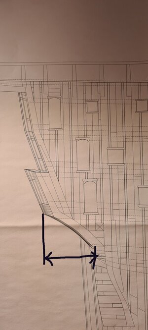
I may be able to correct those three to four millimeters in the above-mentioned 'supports' to get back to the dimensions the drawing is based on as quickly as possible and to prevent further impact.
Before I start this I still have to check all the dimensions, because according to the drawing the top beam is correctly placed against the keel, so perhaps it is better that I should leave everything for what it is.
I have measured it more closely based on the drawings, and I suspect the deviation is less than it seems. I intend to solve it like this...
A piece of framing still needs to be placed between the rear frame and the rear part, which is now a bit too far forward. With the help of this part I can apply some force to the back part to force it into place. In order to do that, I first have to ensure a stable frame that cannot be pushed forward.
Conclusion: I will start by placing the frames on the keel from bow to stern, so that a stable base is created. Then I force the back in place.
- Joined
- Aug 8, 2019
- Messages
- 5,568
- Points
- 738

I spent quite a long time looking at your pictures to see what was wrong. Hard to perceive this. But as you say, this could be a solution. What you can then also do is at the touch points where that rear meets the frames. There on the horizontal beams outward and inward give some more meat. You sand that flush with the frames afterwards.
Ik heb best lang naar je foto's gekeken om te zien wat er mis was. Moeilijk om dit waar te kunnen nemen. Maar zoals je zegt kan dit een oplossing zijn. Wat je dan ook kan doen is op de raakpunten waar die achterzijde de frames raakt. Daar op de horizontale balken naar buiten en naar binnen wat meer vlees te geven. Dat schuur je naderhand gelijk met de frames.
Ik heb best lang naar je foto's gekeken om te zien wat er mis was. Moeilijk om dit waar te kunnen nemen. Maar zoals je zegt kan dit een oplossing zijn. Wat je dan ook kan doen is op de raakpunten waar die achterzijde de frames raakt. Daar op de horizontale balken naar buiten en naar binnen wat meer vlees te geven. Dat schuur je naderhand gelijk met de frames.
Thank you for the trouble to study the photos! I am not sure what you mean though...That would be a possibility if I still had to make the horizontal beams, but they have already been fixed...I spent quite a long time looking at your pictures to see what was wrong. Hard to perceive this. But as you say, this could be a solution. What you can then also do is at the touch points where that rear meets the frames. There on the horizontal beams outward and inward give some more meat. You sand that flush with the frames afterwards.
Ik heb best lang naar je foto's gekeken om te zien wat er mis was. Moeilijk om dit waar te kunnen nemen. Maar zoals je zegt kan dit een oplossing zijn. Wat je dan ook kan doen is op de raakpunten waar die achterzijde de frames raakt. Daar op de horizontale balken naar buiten en naar binnen wat meer vlees te geven. Dat schuur je naderhand gelijk met de frames.
- Joined
- Jul 20, 2022
- Messages
- 77
- Points
- 143

Hello,
I made this stern almost 10 years ago. I had previously modeled it in 3D. It is a very difficult area to assemble because of the different angles between the parts. To build it I made a template that allowed me to do it without any problem.
There are no drawing errors, all the parts have to be made very precisely.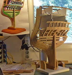
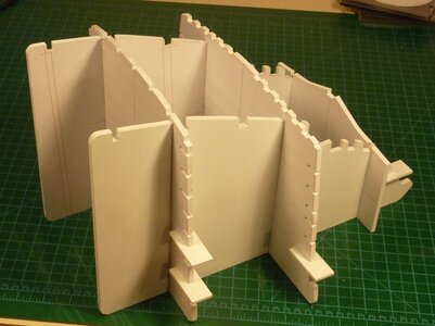
Bernard
I made this stern almost 10 years ago. I had previously modeled it in 3D. It is a very difficult area to assemble because of the different angles between the parts. To build it I made a template that allowed me to do it without any problem.
There are no drawing errors, all the parts have to be made very precisely.


Bernard
Hi Maarten, a while ago you asked for a stack of frames. I couldn't show it at the time, but now I canHi Ronald,
Maybe for you boring but for us not. We want to see some pictures of your huge stack of frames.
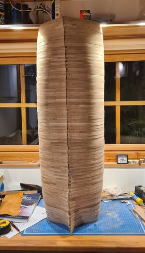
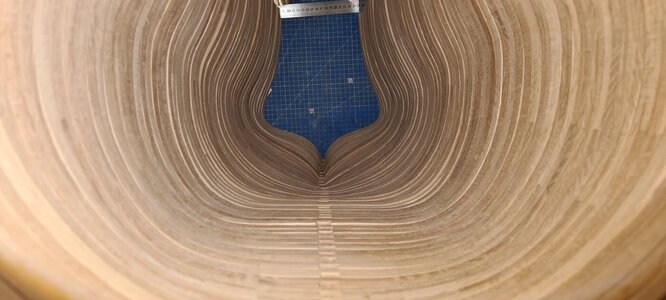
Like mentioned earlier, I will start to fix the frames on the keel. First I do a final check comparing it to the drawings to see if the shape is still exactly als drawn, then I will, if applicable, add some markings like where the deckframes will be, then a final check if the frame is at the desired position on the frame whereafter I add spacers and glue the frame to the keel....
Hi Bernard,Hello,
I made this stern almost 10 years ago. I had previously modeled it in 3D. It is a very difficult area to assemble because of the different angles between the parts. To build it I made a template that allowed me to do it without any problem.
There are no drawing errors, all the parts have to be made very precisely.View attachment 334918
View attachment 334919
Bernard
This looks really great! A really fine example of craftsmenship... Looking at this makes me realize I want to go too fast...., and then mistakes are made.... I hope I can make it look better after I finish the hull with sandpaper....
I try to follow the drawings as best as I can, but what happened here is that I thought that de drawing had a fault... Maybe so, maybe not... But I went on before really studying what te problem was....
- Joined
- Sep 3, 2021
- Messages
- 5,190
- Points
- 738

Now that's what I would call a full stack!Hi Maarten, a while ago you asked for a stack of frames. I couldn't show it at the time, but now I can
View attachment 334920
View attachment 334921
Like mentioned earlier, I will start to fix the frames on the keel. First I do a final check comparing it to the drawings to see if the shape is still exactly als drawn, then I will, if applicable, add some markings like where the deckframes will be, then a final check if the frame is at the desired position on the frame whereafter I add spacers and glue the frame to the keel....
Hi Ronald, unfortunately these things are part of our hobby but convinced you find a good solution.
From the pictures it is hard to see the issue, but can it be the height of the stern frames instead of placing them more foreward or aft. This as the open space between the most aft full frame and the stern is wedge shaped and becomes more narrow towards the bottom. Placing the stern frames lower will fill the space.
Just a thought.
- Joined
- Aug 8, 2019
- Messages
- 5,568
- Points
- 738

Then it's to late. I ment to let them stick out on the outside and inside.Thank you for the trouble to study the photos! I am not sure what you mean though...That would be a possibility if I still had to make the horizontal beams, but they have already been fixed...
Hallo Bernard,Hello,
I made this stern almost 10 years ago. I had previously modeled it in 3D. It is a very difficult area to assemble because of the different angles between the parts. To build it I made a template that allowed me to do it without any problem.
There are no drawing errors, all the parts have to be made very precisely.View attachment 334918
View attachment 334919
Bernard
many thanks for showing us your stern section - it is hard to see, which one is the 3D design and which one the real (wood) model.
Great work (also the template) - I hope to see more of your work - much more (maybe in a log of your actual (or also older) project(s)
Very impressive - and very accurate production of these frames - Bravo!!!!Hi Maarten, a while ago you asked for a stack of frames. I couldn't show it at the time, but now I can
View attachment 334920
View attachment 334921
Like mentioned earlier, I will start to fix the frames on the keel. First I do a final check comparing it to the drawings to see if the shape is still exactly als drawn, then I will, if applicable, add some markings like where the deckframes will be, then a final check if the frame is at the desired position on the frame whereafter I add spacers and glue the frame to the keel....
- Joined
- Oct 17, 2020
- Messages
- 1,691
- Points
- 488

Hello Ronald, I'm sorry, I can't understand (translation), what's the problem with your model, ThanksHi Maarten, a while ago you asked for a stack of frames. I couldn't show it at the time, but now I can
View attachment 334920
View attachment 334921
Like mentioned earlier, I will start to fix the frames on the keel. First I do a final check comparing it to the drawings to see if the shape is still exactly als drawn, then I will, if applicable, add some markings like where the deckframes will be, then a final check if the frame is at the desired position on the frame whereafter I add spacers and glue the frame to the keel....
Regards Frank


