LE ROCHEFORT

As seen in your photo, the foot of frame 29 is almost there.... but it is wrong. If you leave it as is, it will sit to high: you are basically doubling the size of the rising wood.

Frame 28, 29, 30, 31 and 32
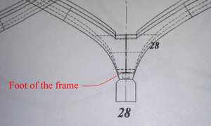
The foot of these frames are similar: the only difference is that they sit higher as they get closer to the stern.

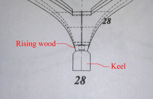
Here are some illustrations for frames 28 as an example:

Photo 1
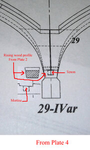
What is what? Especially the rising wood.

frame 28 a.jpg

Photo 2
No treenail here...
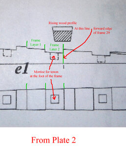
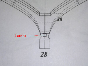
The foot of the frame is secured to the rising wood by a square tenon. The tenon should be shaped as part of the foot of the frame.
The tenon is fitted into a mortise cut into the rising wood.
If you do not feel comfortable in cutting / shaping the tenon and the mortise, you can replace them by drilling a hole in the foot of the frame and the rising wood and then, insert a thin "dowel" (approximately 2 mm diameter).

frame 28 b.jpg

Photo 3
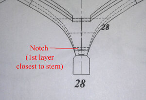
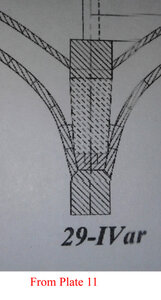
Description of the lines representing the lower edge of the foot of the 2-layer frame, and ultimately showing the notch to be cut.
Starting at the line representing the top of the keel (2nd solid line from the bottom of the keel) and not taking into account the tenon (shown in the photo above)

- the next line up (solid line) represents the forward edge of the foot of the frame or also, the top edge of the rising wood. Basically the forward edge of the top layer of the frame.

- the next line up (dotted line), the one very close to the solid line described above, represents the back edge of the foot of the frame sitting on the rising wood. Basically, either the back edge of the top layer or the front edge of the bottom layer of the frame.

- the next line up (dotted line) is the back edge of the foot of the frame, closest to the stern. Basically the back edge of the bottom layer of the frame.
frame 28 c.jpg

Hope this helps.
G.
 
Last edited:
Here is the illustration as to why your frame 29 is not right.

The lower edge of the foot of the frame should be located as shown in the post above: basically at the top edge of the tenon (the small square traced within the foot of the frame).
The area around the tenon is the rising wood. If it stays this way, you will have essentially doubled the height of the rising wood. As a result your frame sit that much higher that it should be. Furthermore the overall shape of the stern area of your ship will be wrong as the curves and general lines of the stern will be moved higher.
Hope this makes sens.

20200506_173047 (1).jpg


This is an easy fix, just go to your disk sander and sand the foot to the solid line as shown in my previous post (almost to the top of the tenon).

G.
 
Last edited:
Hi Gilles, WHERE DO I MAKE THE CUT TO GET TO THE RIGHT HEIGHT, CAN YOU SHOW IT IN THE PICTURE, IN A COUPLE OF MINUTES, I WILL POST PICTURE of FRAME No.28, AND THE RISING WOOD G1 ATTACHED TO THE KEEL ASSEMBLY, and how do my frames look overtall and have i got the HORIZANTAL CUTS CORRECT. AS ALWAYS GOD BLESS STAY SAFE Don
 
YOU ANSWERED MY QUESTION BEFORE I POSTED IT ARE ALL THE FRAMES FROM 28 TO 32 AND FROMTHE BOW WHAT FRAMES GET THIS IS IT FROM FRAME 5 FORWARD or WITCH one. AS ALWAYS GOD BLESS STAY SAFE Don
 
YOU ANSWERED MY QUESTION BEFORE I POSTED IT ARE ALL THE FRAMES FROM 28 TO 32 AND FROMTHE BOW WHAT FRAMES GET THIS IS IT FROM FRAME 5 FORWARD or WITCH one. AS ALWAYS GOD BLESS STAY SAFE Don


If you look at plate 2:
at the stern
- part e1 has 3 little squares (mortises) traced in there towards the back: those are frame 28, 29 and 30
- part g1 has 2 square as well: frame 31 and 32

at the front
- part f2 has 2 square as well: those are frames 1 and 2

All this can also be seen in plate 4 as well: within the darker grey area highlighting the longitudinal framing or axis of the ship.

G.
 
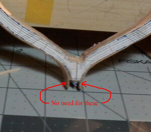
If this is frame 28: no need to leave these "lips" (lets call them that way). If you do not need them, do not have them.

The same applies all the way to frame 32.

20200508_014748.jpg

As for the front, looking at the frame templates
- you need tiny "lips" on frame 2
- you do not need any on frame 1: if you do not need them, don't have them


A piece of advise in regards to these "lips", make sure you leave enough meat for them (keep them extra thick) and make sure you adjust them to fit as snug with the rising wood and keel as possible. If the fit is loose, they will break off when you sand the hull later. Do not worry if they cover the rabbet, you can always re-work the rabbet after sanding the hull when assembled. Again, just make sure they are tight, but not too tight as they may break off if you have to push them in too hard.
These things can be a pain in ... you know what.

FYI: the term "lip" is only something I made up for the description, so do not look at that in a marine dictionary, you will not find it as it relates to this part of the frame.


As for the keel and rising wood. To make sure everything is alright, the best way is to check the assembly over the plan.

G.
 
Last edited:
Just because you asked for feedback:
Looking at your keel and rising wood assembly in your photos, it looks like you simplified the notches for the frames.
In the plan, the notches in the rising wood are supposed to be cut in two ways: horizontally to reduce the thickness and and vertically to reduce the width of the rising wood.

It is hard to tell from the photo but it looks like they were cut only to reduce the thickness ... but I may be wrong! It could just be the photo.
If the notches were cut this way, it is OK, as it will make handling the notches in the frames easier.

PS: This feedback is not done to push you to do everything as per the plan: some things can and should be simplified... you are the BOSS.
Just want to figure out if you do "simplify" things in some aspects, as this way, whoever offers guidance will not get hangup in such details and avoid misunderstandings as to what you are doing.

G.
 
Last edited:
YES I DO TRY TO SIMPLIFIE some things, doing OK, GETTING MORE COFIDENT AS I GO ON THE TRUE TEST OF THE FRAMES WILL BE WHEN MY JIG GETS HERE, THAT WILL TELL. GOD BLESS STAY SAFE Don
 
THANK YOU VERY MUCH, THIS IS WHAT WE HAD VISIONED, HOPE YOU FIND IT HELPFUL, THE FRAMES TOOK ME A VERY LONG TIME < A VERY LONG TIME BUT IT WAS WORTH EVERY BIT OF IT, THIS WILL GO ON TO OTHER BUILDS FOR MY FRAMING, WHAT GILLES IS SAYING IS THIS IS NOT THE ONLY WAY TO DO THE FRAMES BUT IT IS MY WAY, there are other ways to do this one way not better then the other as long as the results are correct, hope this has been helpful to other members, THANK YOU AGAIN. GOD BLESS STAY SAFE. Don
 
HI AGAIN GILLES, I AM HAVING A LITTLE PROBLEM UNDERSTANDING the of how far up to sand SORRY ABOUT THIS is it to THE TOP OF THE TENON , therefore when sanded the pattern showing the tenon is gone, SORRY FOR HOW THE EXPLANATION WORKS
 
HI AGAIN GILLES, I AM HAVING A LITTLE PROBLEM UNDERSTANDING the of how far up to sand SORRY ABOUT THIS is it to THE TOP OF THE TENON , therefore when sanded the pattern showing the tenon is gone, SORRY FOR HOW THE EXPLANATION WORKS

Don,
In the past few days you have been making me break my promise: remember: I gave my word....:eek:

It makes no sense for someone to tell you where to cut or sand if you do not understand why.

So if anyone can provide Don with an explanation that would be great.

If not, I will try post the info again, in more detail using different views from the plans you are using.
Make sure you look at plate 2, 4 and 11, the answer is there.
Give me some time to organize an explanation differently from what was posted a couple days ago....

Also, from your latest photos above, looking at your keel assembly you may have a problem when you time will come to install the frames on it: it does not seem like the notches are cut accurately enough: some frames may end up seated too low. That was the reason why I had you keep lots of meat around your frames but I see that they were sanded close to the line and some have been beveled as well. Oh well, you may have to improvise something....

My personal opinion....
Close tolerance is Ok for the average modeler, even a beginner, but for some, especially when you are dealing with physical challenges, it may not a good idea right away unless you are able to be consistent when it comes to building the basis for the structure of the hull. If the first time builder is not able to be accurate, I always suggest building the frames oversize. Further sanding can be done after a first dry fit: just to see how everything fits.
For some it may seem like it is more work and it may be silly, but at least there is no disappointment attached to the need for a second set of frames .
This is also true for any explanations, sometimes long ones: if the modeler does not fully understand a concept, he / she will continue to work in the dark and may end up disappointed.

Just saying ..... and of course I will say it again "I am no expert", "not a teacher", so this must be taken with a grain of salt.

G
 
Last edited:
Hi Gilles yes we need more help here but let us ask DONNIE see what he thinks i anticipated some problems wit the notches an some w2ork will have to be done maybe shims and maybe some wood filler as needed will know when jig gets in, when i test fited the frames my slip they were OK
 
One way to do it is to have a dowel fitted at the bottom of every frame so that they can be secured in place.

I personally would not advise too many shims and too much wood filler.
You may be better off going for the redo. Just my opinion as it would not be time wasted: always strive for the best you can do the 1st time and you do not achieve it, go the a second try. The joints do not have to be perfect, but I am sure you can do better.
Looking at the sternpost knee, you have the same problem.


G
 
Last edited:
HI AGAIN GILLES, I AM HAVING A LITTLE PROBLEM UNDERSTANDING the of how far up to sand SORRY ABOUT THIS is it to THE TOP OF THE TENON , therefore when sanded the pattern showing the tenon is gone, SORRY FOR HOW THE EXPLANATION WORKS

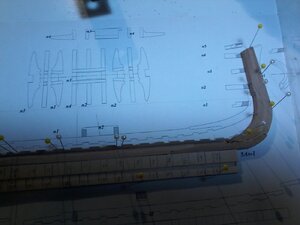
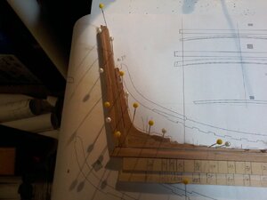
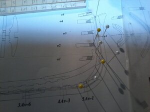
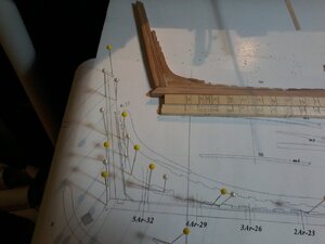
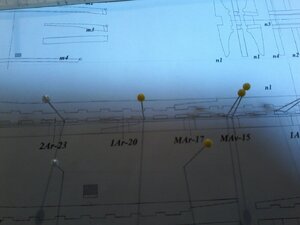
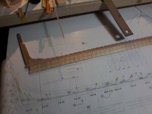
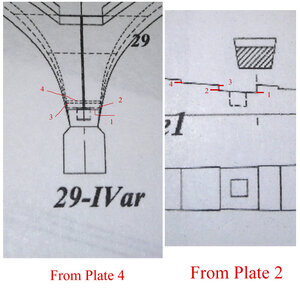
This this frame 29 (towards the stern) but the same is true for every frame.
Where to cut is explained by the location of the lowest edge at the foot of the frame when you look at the frame pattern in plate 4.
But here are different views to help visualize.

20200509_135558 copy.jpg

Pattern lines 29.jpg

20200509_135835 copy a.jpg

20200509_135744 copy.jpg

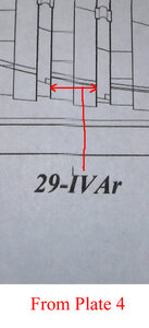
The red lines are only there to show the lines forming the edges of the frame: in this case:
- left red arrow = the back face of the frame (direction stern)
- right arrow = forward face of the frame (direction stem)

Everything about the foot of the frame is shown here (except for the tenon): the lines representing (at the same time) the top of the rising wood and the base of the frame: the lines below the arrows. Remember "no lip" at the foot of the frame: the width at the bottom of the frame is the width of the top of the rising wood.

20200509_160232 copy a.jpg

G
 
Last edited:
HI GILLES THANK YOU your sugestion about a dowel in each frame is a good one, i will check the depth of the KEEL NOTCHES WITH MY DEPTH GAUGE and COMPARE IT TO THE PLANS, I THINK I WILL HAVE MORE OF A PROBLEM WITH THE WIDTH OF THE NOTCHES BEING THE SAME, AND THE FRAME NOTCHES THEM SELVES, WE WILL SEE WHEN JIG COMES IN had a BIG, BIG VERY BIG SUPRISE TODAY MY DAUGHTER AND SON- IN-LAW, reaaranged my total apartment, my bed room is not my living room, my LITTLE HOBBY ROOM IS MY COMPUTER ROOM, AND MY OLD BEDROOM IS A REAL WORK ROOM I WILL POST PICTURES FOR ALL TO SEE, GOD BLESS STAY SAFE Don
 
Back
Top