LE ROCHEFORT

Don,

If you like you can simpify the tenon with a brass pin. Nobody will see this on the finished model.
Also by English ships, you have this kind of construction at the stern. Try to build what you can see on the finished model.
To build such a model is a really long and challeging journey. I learned a lot for about French ship building throug the converstaion between Gilles and you.
 
I THINK I WILL HAVE MORE OF A PROBLEM WITH THE WIDTH OF THE NOTCHES BEING THE SAME, AND THE FRAME NOTCHES THEM SELVES.

One important note to remember...
In the joint between 2 parts, if one part is simplified, make sure the 2nd part is adapted to fit the first.
And in the end, if the joint is not visible, it can be simplified further: but you need to think it through.
For example: all the frames where there is a "lip" covering the joint (most of the frames), you could have made a 1 size notch in the rising wood to receive a 1 size notch cut into the width of an assembled frame. Which mean... building the frame would have been a bit easier,: as the 1 size notch could have been cut once the frame was assembled, which could have help in the alignment of the layers.
The notches were a concerned throughout the building of most of you frames, and most of your concerns on this subject would have been alleviated at least for these frames.

G.
 
YEP, IT SURE WOULD THIS IS FOR THE NEXT ONE, WILL REMEMBER, fantastic information AND YES YOU SHOULD PRODUCE A BOOK BASED ON OUR LOG, JUST YOU NOT ME, LOL. GOD BLESS STAY SAFE Don
 
THANK YOU CHRISTIAN, this is WHAT GILLES AND I HAVE WANTED CHIP IN, MAARTEN and others what a great learning experience this is totally enjoyable PROBLEMS AND ALL. GOD BLESS STAY SAFE Don
 
Hi Maarten, IF YOU KNOW OF A DIFFERENT WAY TO DO THINGS PLEASE CHIP IN it is what BOTH GILLES AND MYSELF WANT NO ONE WAY IS THE ONLY WAY TO DO THE PROCEDURE , YOURS AND CHRISTIAN COMMENTS ON THE FRAMES BY USING A FULL PATTERN WAS JUST WHAT I NEEDED AS GILLES SAYS HISV WAY IS NOT THE ONLY WAY, AND HE DOES HAVE A SET OF PLANS, SO I DO NOT KNOW IF ANYONE ELSE DOES, EAGERLY AWAITNG THE JIG COMING IN IN A COUPLE OF WEEKS, THIS WILL TELL. GOD BLESS STAY SAFE Don
 
THANK YOU KURT THIS IS WHAT WE ARE STRIVING FOR, for me if it ends right now, to me it is 90% acomplished, but with the help we will continue. GOD BLESS STAY SAFE Don
 
Hi Don,

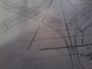
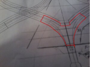
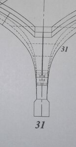
I see you dotted the outline on the fra.e 31, but keep in mindit are two frames which differ in shape due to the narrowing of the ship. On the bottom side your line is correct on the top you shpuld be one line lower.
See in the picture below.
Rochefort frame 31.JPG
But please provide a better scan of the drawing as the picture is out of focus and I easily can miss a dotted line.
 
Last edited:
THANK YOU MARRATEN I will take better pictures, from now on and also closer views, got my main room just about finished just need a couple of lamps. GOD BLESS BE SAFE Don
 
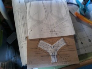
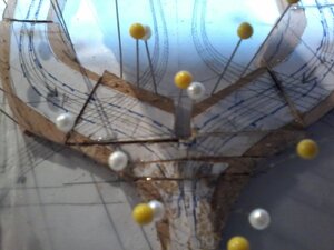
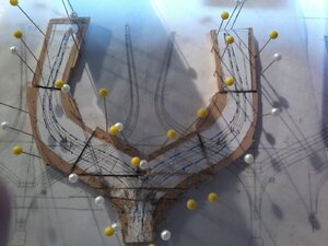
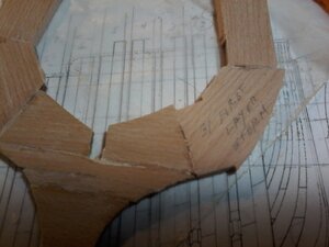
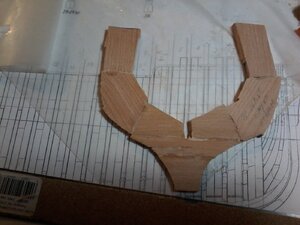
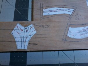
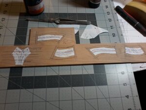
hope these pictures are better if not do i need more light or what here goes pictures of FRAME No.31 first layer(facing stern) all put together spots on front and back are a drop of CA to reinforce joints the joints are tight where it counts around the FRAME FINISH, and prep for 2nd layer (facing bow) am i on the right track for these last frames will do the final keel finish line on the disk sander after both layers are put together making up the complete FRAME and i will correct the keelson notch on the first layer PLEASE IF THE PICTURES ARE NOT CLEAR ENOUGH LET ME KINOW20200514_022022.jpg20200514_021920.jpg20200514_023429.jpg20200514_023537.jpg20200514_024641.jpg20200514_024729.jpg
 
Hi Don,

check what you sand away from your frames for the installation. I think hat you can cut the frames with much less timber to san away. This makes the hole process much more effektive and simpler
 
Hy Don,

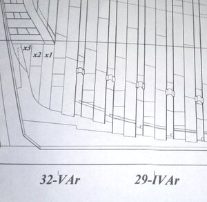
Can you post a picture of the side view drawing of the stern section? You have cut your bottom frame Y piece horizontally 3 times, I don't expect these are lines of individual wood part as this weakens the Y piece enormously. Therefore I'd l;ike to see the side view drawing to check where these lines are coming from.
I would make the Y piece in one cut.

20200509_160232 copy 2.jpg

20200514_093904.jpg

Don,
When you take pictures with your IPad or tablet:
- do not get so close to the plan (take the photos from further away.
- use as much natural light as possible and set it up with auto flash
It will be easier to get images in focus.

G
 
THANKS ALL, MAARTEN GOT THAT FROM BOTH THE MONOGRAPH AND FROM GILLES CHECK OUT ABOUT PAGE 32 onward, having fun again, since BAND SAW HAS NEW BLADE, and i will take pictures of my MODELING ROOM, just about finished. GOD BLESS TO ALL STAY SAFE Don
 
When you take into account the way the timbers would be fitted, their is actually very little loss of strength in the assembly: one could even think that strength could be enhanced.

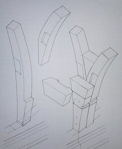
I think that this was posted much earlier but here is a drawing extracted from the "74 gun ship" (Jean Boudriot) showing the detail in the joinery.
Le Rochefort is of course a much smaller ship but built according to the plans......
The timbers would not have been just cut and glued (bolted) together, some joinery would have been required to "lock" the parts together for added strength.

It would be hard to reproduce this style on joinery, even at 1/36 scale: the timber are pretty small.

Furthermore: a similar but simplified exploded view of the foot of a rising frame should be or is included in the monograph: this view would / should show the breakdown (composition) of the frame parts without the complicated joints. I think, every other monograph does.....

And believe it or not, Don is actually doing a simplified version of these frames by skipping one step (his rising-floors are made in 1 piece): besides the joinery which is never (I think) included in the monograph's frame plans .

Anyways, here is the drawing.

20200514_103519.jpg
 
Last edited:
Gilles, that is sure some fancy joinery for the V frame. I can see why you just cut one piece to model on the ship.

Who will ever see it in the model?
Gilles is showing, how the elements of an original 1:1 scale 74-gun ship was made (and not fancy - it was real) - his intention was not to show how it should be done in 1:48 -> with explaining these things it is easier to understand such a monograph drawing
 
Back
Top