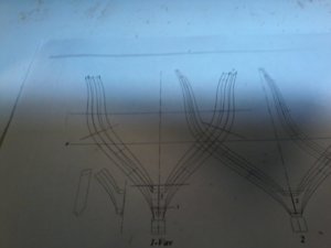
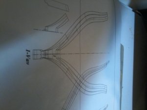
LE ROCHEFORT

Don
I wouldn't worry to much about the keel moving a little,it will all pull true when you put it in the jig.As long as you don't put it in a damp cellar it will be fine.The keel of my Saint Philippe build is like a long piece of knicker elastic and will stay that way until it is finally fitted on the modelROTF

Kind Regards

Nigel
 
hi all more progress, AND I REALLY REALLY< REALLY NEED INPUT ON THIS ONE PLEASE, showing pictures of the hawse timbers using the dutch style( AS PER THE MONOGRAPH) a little history could help, i have cut the hawse timperes and made a template for there installation, before i can do this i need the first frame completed, now the problem the first frame is highly complicated to me as there are some many lines it is driving me batty like me pin method, if some one can tell me if i am on the right track i know the dotted lines are for the bevels whitch i will do latter now to get the rght frame lines, please help maybe NIGEL WH IS FAMILAR WIT THE ANCRE AND GERARDS PLANS OR UWE IF NOT TO BUSY I HAVE TRIED GERARD BUT HE IS VERY BUSY SO LOOKING FOR HELP PLEASE, OH BTW IF PICTURES TO DARK PLEASE LET ME KNOW AND I WILL RE-TAKE THEM20191115_025827.jpg20191115_030122.jpg20191115_030402.jpg20191115_030402.jpg20191115_040539.jpg
 

Attachments

  • 20191115_025953.jpg
    20191115_025953.jpg
    90.5 KB · Views: 6
  • 20191115_041104.jpg
    20191115_041104.jpg
    107.5 KB · Views: 7
Hi Don
I also have a problem with view 1-Vav.It shows only a single thickness of frame at the keel.The gap above this I see you have drawn a pencil line across horizontally.There would be a line here if the frame was double thickness.If the futtocks on the far side of the frame terminate either side of the keel you would expect to see two dotted lines vertically either side of the keel.Is there a separate timbering drawing showing the futtock parts on the far side of the frame?
The rest of this section is fairly self explanatory,just cluttered.It is the bottom of the frame that is unclear.Trying to explain things in words is also awkward.If necessary I will do some sketches this weekend to help if we are still struggling to solve the problem'

P.S.If you think this is bad,you want to see this section for the front frame of Saint Philippe,it is horrendous!

Kind Regards

Nigel
 
They say a picture is worth a thousand words Don.Here is a link to a build on Gerard's forum.It does appear a line is missing at the top of the crutch where you have drawn one in.


Kind Regards

Nigel
 
Hi NIGEL, IF THIS DETAIL IS BOTHERING YOU think of poor me first time with this(LOL), looked at the pictures on his forum i still can not visulize the notches bot the keel and keelson notches i can understand them on the other frames but not on frame No. 1, another question pops up on the hawes details are the filler pieces at a set height that can be taken off the plans, any other help will be GREATLY APPERICATED. THANKS AGAIN Don PS ONCE AND FOR ALL I NEED TO UNDERSTAND THAT FRAME No. 1 IS A DOUBLE IT LOOKS LIKE IT FROM OTHER VIEWS, then that means that all the frames are double frames, I WILL TAKE A PICTURE OF THE DETAIL SHOWN IN THE MONOGRAPH, YOUR HELP IS INVALUBLE TO ME. SO THANKS SO MUCH Don
 
Don
I am confident the first frame on Rochefort is a double frame around it's full circumference.There are several builds on Gerard's forum but are inconsistent regarding where the futtock join falls in this area.One build has the futtocks on the hawse timber side joined vertically in the keel's centreline,another has a horizontal join just above the top of keel.
Just because the first frame is a full double does not mean all the frames are.Saint Philippe has a full double first frame.My interpreptation is that none of the others are.I believe other builder's have misinterpreted JC Lemineur's drawings.Lemineur also did a monograph of La Francois.Russian master modeller Narim Maygeldinov built this vessel to the monograph and his framing differs from other modellers. I believe his interpretation is correct.
Is there any clues in the book that accompanies the plans,I do know it includes several sketches of the timbering in this area?

Kind Regards

Nigel
 
Nigel, a very exciting site, many tips and techniques we can learn from, I'll look into the site later, thanks.
BDW, DON, Good progress, it is clear that there are many challenges to building in this way,
I'm also heading into that world with my Rattlesnake project, good luck,
 
Nigel, a very exciting site, many tips and techniques we can learn from, I'll look into the site later, thanks.
BDW, DON, Good progress, it is clear that there are many challenges to building in this way,
I'm also heading into that world with my Rattlesnake project, good luck,

Knut the site is brilliant,but my French isn't otherwise I would have joinedROTFIt can be very useful to see how several people have approached the same issue when interpreting these drawings.Issue for me is,no member has built the Saint Philippe yet:rolleyes:

Kind Regards

Nigel
 
YOUR BUILD NIGEL IS ONE OF A KIND IN ALL RESPOECTRS NO ONE CAN COME CLOSE,,,,,, I WILL SENP PICTURES FROM THE MOINOGRAPH OF THIS SECTION, THE RESTOF THE FRAMES I THINK I UNDERSTAND WHERE AND HOW THE NOTCHES GO, I APPRECIATE ALL THEB HELP NIGEL> THANKS Don
 
Thank you Don,I am genuinely lost for words with that compliment.The important thing to remember is everyone started somewhere and together we can help each other to become more proficient in our hobby.That is what this forum is all about.So send me your pictures and together we will try and resolve this issueThumbsup

Kind Regards

Nigel
 
here are more pictures showing dry fitting of frame No. 1 also pictures from monograph showing how framwes are made ( HOPE THIS IS WHAT YOU NEED NIGEL) finally from plans showing frame type and location on the inner keel, ,,,one other question there ar some additional small marke on plans by monogrph it says for deck location can these be the deck clamps. AGAIN NIGEL THANKS FOR ALL HElP20191116_200819.jpg20191116_202732.jpg20191116_202941.jpg20191116_203204.jpg20191116_203500.jpg20191116_203554.jpg
 
Ok Don

Here is my interpretation,the bow side of the first frame is split as you have it in the trial assembly,the other side(facing the stern) has a vertical join on the centreline of the keel.The top of the floor(where the keelson) fits has a plain slope across BOTH frames.I deduce this by looking at the keelson drawing.This does not show a notch in the position of the first frame.You can check the position of the notch by drawing the double frame thickness onto your keel plan.It is simply a case of measuring from the keel to the bottom of the keelson in this position.You will get a smaller height for the stern side of the frame and a taller one for the bow side.Transfer these two heights onto the framing drawing then you will know where the slope falls.If in doubt I will post a sketch tomorrow.
Regarding the marks,on Saint Philippe,I have two little marks.I believe the lower one is the top of the deck at the waterway,the higher one is top of deck on ships centreline.The top of the deck clamp sits much lower.

Kind Regards

Nigel
 
Don
Apologies for the poor drawing and the fact I am trying to take a picture on a very miserable day with artificial lighting.

First draw the position of the first frame on the plan you were working to first which shows the keel and keelson in one complete view.Before you do though, you must check on the drawing that shows the frames sat on the keel that they are indeed 90 degrees to the keel.If not you can make a card template for the angle to draw the frame faces rather than using a square.

Next measure vertically from the base of the keel the height to the bottom of the keelson at the two points I have circled,this will give you the front and back position of the slope on top of the crutch.

Hope this helps

Kind Regards

Nigel

roche1.jpg
 
Back
Top