POF La Palme (L'Amarante) Corvette 1744 1:36 (Ancre Monograph) by Tobias

Hello everyone,
@dockattner @Rpope @Jimsky @mtbediz1 @pianoforte @Ptèr @Steef66 @Uwek @Mirek
Thank you for your comments and the appreciation and everyone who left a like as well. I'm a bit overwhelmed by so much positive feedback.

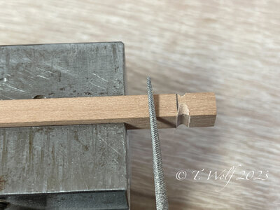
Hello Paul, as promised, my way of making the knight heads by hand:

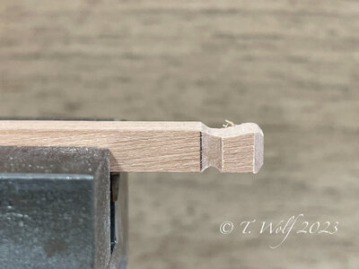
I mark the square once completely all around.
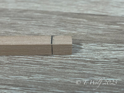
eZy Watermark_17-04-2023_06-08-50-8660PM.jpeg

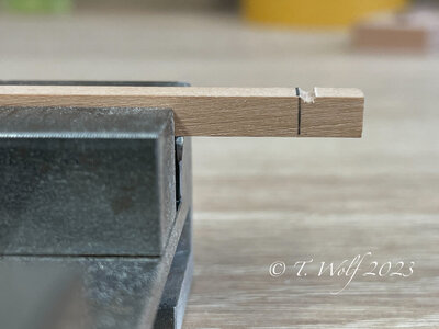
With a small needle file (round) I file a groove on all four sides.
eZy Watermark_17-04-2023_06-10-27-7230PM.jpeg

The depth is a matter of feeling

eZy Watermark_17-04-2023_06-12-52-7180PM.jpeg

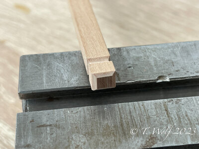
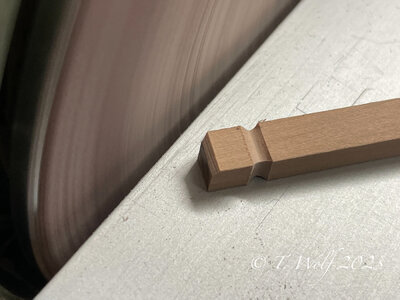
In the next step, I bevel the edges at the top a bit with the disc sander. Oh not entirely by hand, sorry. ROTF
eZy Watermark_17-04-2023_06-14-51-9120PM.jpeg

eZy Watermark_17-04-2023_06-15-30-2150PM.jpeg

Now I file the incline with a half-round needle file, all on all sides. Finally, I break up the resulting edges and finish with steel wool. Please don't ask me about the grit, I threw away the banderole.
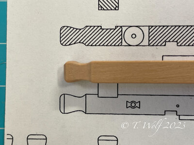
eZy Watermark_17-04-2023_06-17-55-6980PM.jpeg

eZy Watermark_17-04-2023_06-24-43-7270PM.jpeg

Here are the file and the steel wool. The file are from horse cut 1
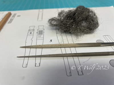
eZy Watermark_17-04-2023_06-26-45-9130PM.jpeg

I hope I could help and thanks again.
 
A fine bit of photos and instructions, they look grand when finished.

One thing I enjoy on this forum is the fact that others are always willing to share the what & how, and teach us how to make our models better.

Hi Kurt, thank you for your words.

I have discussed this topic with @Olivers Historic Shipyard before, unfortunately often only the end result is shown and how what is done is lost. In our opinion, it is also very tiring for some modellers after the umpteenth ship to always go into the same thing, understandably so. I try to describe this as much as possible, because I am also happy about any information I can get, especially about La Palme (L'Amarante). Here in the forum I can only ask Ricci @Giampy65 , as he is the only one who has already built this ship. I also get a lot of information from the French forum from G.Delacroix and the other members.

Translated with www.DeepL.com/Translator (free version)
 
Witaj
Piękna precyzyjna praca brawo .Pozdrawiam Mirek

Hello
Beautiful precise work bravo .Regards Mirek
 
Last edited by a moderator:
very accurate work - Bravo!

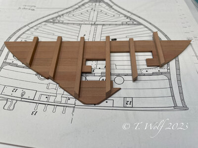
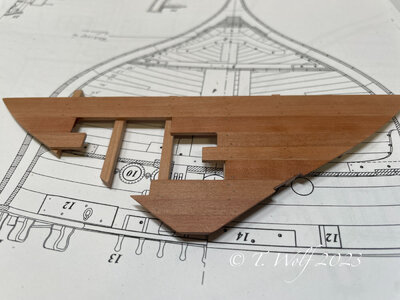
Looking at your photo, a question is coming up once more, a question which I tried in the past to find some answers in publications, but did not find a final answer until now, but maybe we can discuss it here.

How were the bulhead walls fixed on a real ship

there were vertical beams and the boards were nailed horizontal fixed to these beams. that is clear
But how ere the endings of such boards fixed towards the inner hull planking?
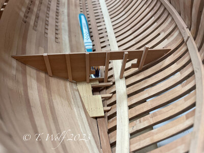
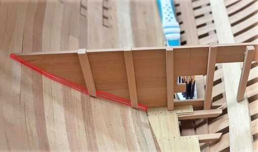
I installed already on some models a small wooden strip, the endings of the boards could have nailed against these stripe. (see photo)
But I am not sure, if this was done in such a way?

eZy Watermark_18-04-2023_07-52-07-9210PM.jpeg

I see in moment no other way, but maybe somebody has a knowledge or suggestion.
One additional advantage in our models is also, that the slightly visible gap between wall and planking will be covered by the stripes

PS: Under the waterline of the ships these walls were fixed and not removable like above the waterline (to protect splintering of the wood during action and a hit by a canonball)
 
very accurate work - Bravo!

Looking at your photo, a question is coming up once more, a question which I tried in the past to find some answers in publications, but did not find a final answer until now, but maybe we can discuss it here.

How were the bulhead walls fixed on a real ship

there were vertical beams and the boards were nailed horizontal fixed to these beams. that is clear
But how ere the endings of such boards fixed towards the inner hull planking?
I installed already on some models a small wooden strip, the endings of the boards could have nailed against these stripe. (see photo)
But I am not sure, if this was done in such a way?

View attachment 370040

I see in moment no other way, but maybe somebody has a knowledge or suggestion.
One additional advantage in our models is also, that the slightly visible gap between wall and planking will be covered by the stripes

PS: Under the waterline of the ships these walls were fixed and not removable like above the waterline (to protect splintering of the wood during action and a hit by a canonball)

Hello Uwe here is the answer from GD

Answer from G.Delacroix Translation from the french forum:

Hello,

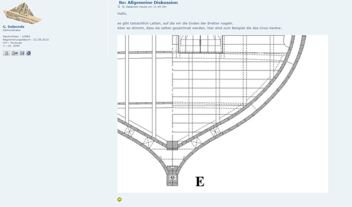
there are indeed battens on which we nail the ends of the boards.
But it is true that they are rarely drawn, for example, here are those of the Gros-Ventre:

1681898833964.png
 
Hello Uwe here is the answer from GD

Answer from G.Delacroix Translation from the french forum:

Hello,

there are indeed battens on which we nail the ends of the boards.
But it is true that they are rarely drawn, for example, here are those of the Gros-Ventre:

View attachment 370046
I am very happy to here, that my thoughts were correct
 
I am very happy to here, that my thoughts were correct
Uwe that with the battens went me yesterday evening also by the head. As I see it, these are only on one side of the bulkhead and also have the same width as the posts. In any case, I will install them. Today I'll start with the upper joist.
 
Uwe that with the battens went me yesterday evening also by the head. As I see it, these are only on one side of the bulkhead and also have the same width as the posts. In any case, I will install them. Today I'll start with the upper joist.
From statical point of view they could be definitely smaller than the posts, because they do not have to take over forces like the weight of board by the posts
- it is only necessary that the board can not move - so I think smaller than the posts
 
Catching up Tobias. Wonderful work you do. Thanks for taking the time to show us your approach hand crafting with precise tolerances. I really enjoy your work for sure.
 
Hello model building comrades,

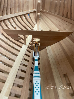
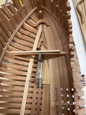
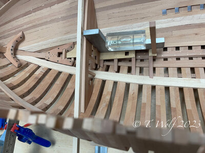
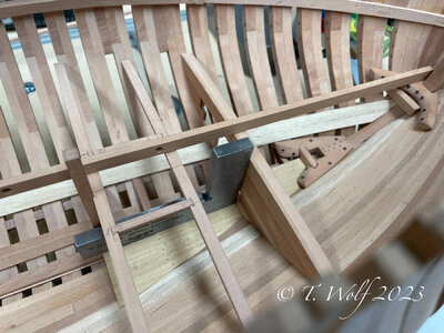
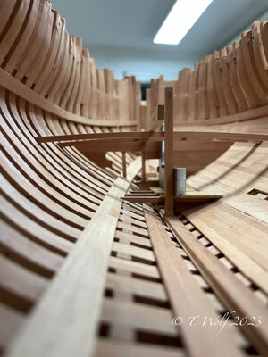
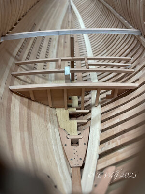
another chest hook has received its bolt and has been fitted. Something went wrong and I was 5mm too deep without noticing it, after measuring again I corrected it. The second floor of the rope room followed, in the rear support a notch was milled into which the upper and last beam of the intermediate deck engages. To check if all heights fit I put a cross member on the three points (chest hook, bulkhead and last beam) and the disaster continued and my bulkhead was 3mm too high so I had to adjust this too, but it has to be rebuilt , it fits but I'm not completely satisfied. Now here are some pictures, everything is loose and not glued so there is still some air everywhere.

eZy Watermark_23-04-2023_07-12-16-4380PM.jpeg

eZy Watermark_23-04-2023_07-13-05-2840PM.jpeg

The height is corrected in the following images.

eZy Watermark_24-04-2023_06-38-51-1600PM.jpeg

eZy Watermark_24-04-2023_06-40-11-7680PM.jpeg

eZy Watermark_24-04-2023_08-08-58-2220PM.jpeg
 
Witaj
Super praca bardzo podoba mi się. Pozdrawiam Mirek

Hello
Great job I like it very much. Regards, Mirek
 
Last edited by a moderator:
You are making the Schwalbenschwanz / dovetail - connections?!?!
Remember, when you do this in the hold already, you will have a lot more on the higher decks ..... Bravo
 
Back
Top