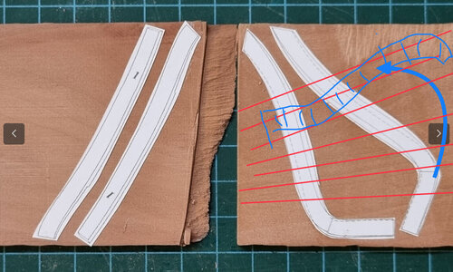
Hi Shota, I have seen other builders pay particular attention to the grain of the wood when creating these frames (and other pieces) in order for them to be strongest in the vulnerable areas. Just a thought....
-

Win a Free Custom Engraved Brass Coin!!!
As a way to introduce our brass coins to the community, we will raffle off a free coin during the month of August. Follow link ABOVE for instructions for entering.
-

PRE-ORDER SHIPS IN SCALE TODAY!
The beloved Ships in Scale Magazine is back and charting a new course for 2026!
Discover new skills, new techniques, and new inspirations in every issue.
NOTE THAT OUR FIRST ISSUE WILL BE JAN/FEB 2026
You are using an out of date browser. It may not display this or other websites correctly.
You should upgrade or use an alternative browser.
You should upgrade or use an alternative browser.
POF L'Amarante Corvette de 12 canons 1744 1:36 (Ancre Monograph- Gérard Delacroix) By Shota
The importance of the grain direction was already mentioned - it is important, otherwise the frames could easily brake.
The old shipwrights made it in the same way


photos from the Museum in Hamburg
You will need slightly more wooden sheets, but it is worth to do so.
Another point will be also, that you, when you finished the hull structure, that the appearance of the wood surface will look better
The old shipwrights made it in the same way


photos from the Museum in Hamburg
You will need slightly more wooden sheets, but it is worth to do so.
Another point will be also, that you, when you finished the hull structure, that the appearance of the wood surface will look better
Dear Shota. Let us just say you have explored and found the boundaries of this type of wood .
Although I pay attention to the grain of the wood, occasionally a piece of wood is broken bending it too extreme or too fast.
Although I pay attention to the grain of the wood, occasionally a piece of wood is broken bending it too extreme or too fast.
- Joined
- Oct 23, 2018
- Messages
- 886
- Points
- 403

- Joined
- Apr 20, 2020
- Messages
- 6,242
- Points
- 738

Hi Shota,
sometimes it is helpful to fake a bigger part by glueing two smaller parts together to get a good grain direction. The picture shows the floor timber which I build from to parts.
View attachment 410920
What an interesting project You started. I will follow this log.
Dear Shota. Let us just say you have explored and found the boundaries of this type of wood .
Although I pay attention to the grain of the wood, occasionally a piece of wood is broken bending it too extreme or too fast.
The importance of the grain direction was already mentioned - it is important, otherwise the frames could easily brake.
The old shipwrights made it in the same way
View attachment 410416
View attachment 410417 View attachment 410418
photos from the Museum in Hamburg
You will need slightly more wooden sheets, but it is worth to do so.
Another point will be also, that you, when you finished the hull structure, that the appearance of the wood surface will look better
my dear friendsI agree with Paul and Tobias. I learned this to by experience. It breaks when in the wrong direction to easily. But love the 'rozen' carf knife of you. Good thing to do a lot by hand. That gives always a good result.
thank you very much for your help and explanations for the method of work and for your kind words
- Joined
- Apr 20, 2020
- Messages
- 6,242
- Points
- 738

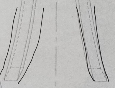
Now I have questions for Tobias and anyone who knows/can help
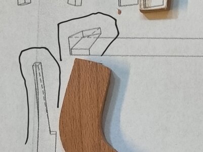
1. How to create the apparent slope in the current halves of the frames
(I am attaching a picture with the drawing and what I built, as well as the area with a black line that I am having difficulty with)
When I was looking at Tobias and Giampy65's build, I'm not sure I noticed that little bend


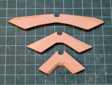
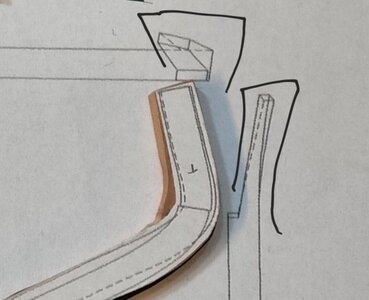
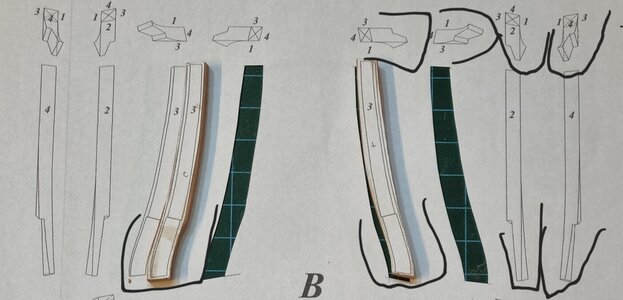
The next subject in which I have difficulty understanding the way of working and reaching the required result is in regards to the way of creating the connection of the split frames connecting to the Transom beam and the Wind transom.
In the first attempt I made the connection areas of the two parts straight and without bending/angle and when I tried to glue the frames to the Wind transom there was a gap of about 1.8 mm. After re-examination I understand that I am required to make the connection areas inclined at a small angle/bending, But I don't know what the right and appropriate
method


The first two pictures are from the first attempt and the next one is from the second attempt before sanding and gluing as well as marking the bending areas at an angle

thanks in advance for your help and guidance
1. How to create the apparent slope in the current halves of the frames
(I am attaching a picture with the drawing and what I built, as well as the area with a black line that I am having difficulty with)
When I was looking at Tobias and Giampy65's build, I'm not sure I noticed that little bend


The next subject in which I have difficulty understanding the way of working and reaching the required result is in regards to the way of creating the connection of the split frames connecting to the Transom beam and the Wind transom.
In the first attempt I made the connection areas of the two parts straight and without bending/angle and when I tried to glue the frames to the Wind transom there was a gap of about 1.8 mm. After re-examination I understand that I am required to make the connection areas inclined at a small angle/bending, But I don't know what the right and appropriate
method


The first two pictures are from the first attempt and the next one is from the second attempt before sanding and gluing as well as marking the bending areas at an angle


thanks in advance for your help and guidance
I would think that you would cut it to the outside lines and then sand the bevel into it. But that's just my opinion. Maybe the Masters have a better method. 
- Joined
- Aug 8, 2019
- Messages
- 5,571
- Points
- 738

I agree. Best to do is when everything is in place.I would think that you would cut it to the outside lines and then sand the bevel into it. But that's just my opinion. Maybe the Masters have a better method.
Hi Shota, well the parts are a bit tricky and it took me about 3 or 4 tries and it's still not 100% correct. It is also extremely difficult to explain and I hope there are no translation errors.
About frame 52:
It's a bit tricky but in the end not that difficult. I first made the two individual pieces and adjusted the recess piece by piece.
About the extended timbers:
You first cut out the basic shape and then glue on all four sides shown in the plan, then file or mill out the small bevel. In the next step, you can make the actual mould.
- Joined
- Apr 20, 2020
- Messages
- 6,242
- Points
- 738

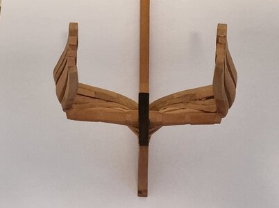
Hello my dear friends
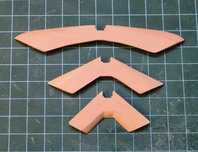
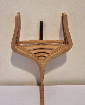
After a week of thorough and patient work, I was able to repair the stern area.
I must thank Tobias and Giampy65's for the most helpful guidance and assistance.
I actually recreated most of the parts: frames 52 and 53, the Transom beam and the Wind transom and the top part from the ebony tree.
I am satisfied with the intermediate result which will allow me to reach the final precisions for all the stern parts and the hull of the ship later on in the construction.
I would like to point out that the dimensions of the frames from the right side to the corresponding edge on the left are the same as the drawing with an accuracy level of tenths of a millimeter, resulting in final accuracy later in the construction.
For now I will let you see the photos of the process and the result


Very nice work my friend. The effort was worth it.
- Joined
- Apr 20, 2020
- Messages
- 6,242
- Points
- 738

thank you very much my dear friend for your kind words and helpVery nice work my friend. The effort was worth it.
Congratulations Shota! It looks like your perseverance has paid off nicely!
- Joined
- Apr 20, 2020
- Messages
- 6,242
- Points
- 738

thank you very much my dear friend for your kind words and complimentCongratulations Shota! It looks like your perseverance has paid off nicely!
Shota, Iam seeing the beginning of a magnificent build here my friend.


