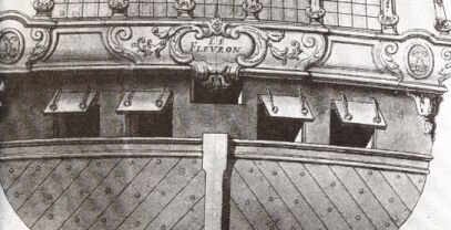
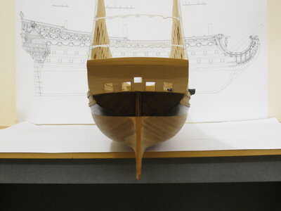
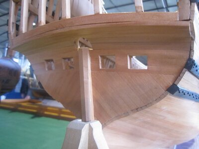
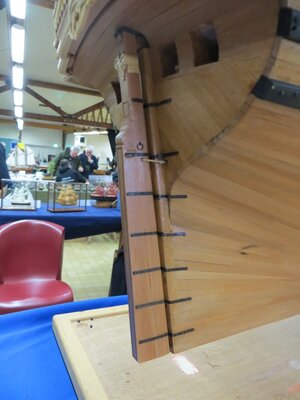
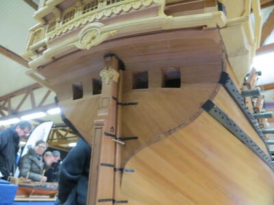
Got to agree with you Marc, VDV really did capture the finer points, with many ships of the 17th Century they really do provide a valuable source of reference
-

Win a Free Custom Engraved Brass Coin!!!
As a way to introduce our brass coins to the community, we will raffle off a free coin during the month of August. Follow link ABOVE for instructions for entering.
-

PRE-ORDER SHIPS IN SCALE TODAY!
The beloved Ships in Scale Magazine is back and charting a new course for 2026!
Discover new skills, new techniques, and new inspirations in every issue.
NOTE THAT OUR FIRST ISSUE WILL BE JAN/FEB 2026
You are using an out of date browser. It may not display this or other websites correctly.
You should upgrade or use an alternative browser.
You should upgrade or use an alternative browser.
Soleil Royal- Re-engineering Artesania Latina's New Kit by NMBROOK
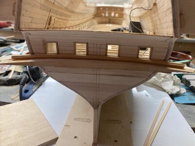
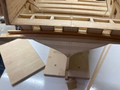
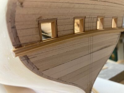
I completed the stern port lining and also created and affixed the rail below the ports.This is boxwood first profiled on the mill and the radius then shaped using a profile cut in the back of a hacksaw blade.
The trim is cut over length and glued to an offcut from cutting the deck beams to conform to the correct radius whilst it is Epoxied to the transom.The ends are then cut off releasing the former.This trim will be notched for the stern post.Much easier to get a natural radius in one piece than trying to get two pieces to flow either side of the sternpost.
Kind Regards
Nigel


Nice moulding! Are you planning to show the entry for the tiller? I cut this opening incorrectly on my model because I copied what Heller had done. Doing so, though, places my tiller with entry above the middle gun deck, when it should enter just below this deck.
Yes Marc,next job at the sternNice moulding! Are you planning to show the entry for the tiller? I cut this opening incorrectly on my model because I copied what Heller had done. Doing so, though, places my tiller with entry above the middle gun deck, when it should enter just below this deck.
That is a great picture Marc, the design is even more convoluted than SR
Yes moulding will match up fine,If you think about it the moulding I have fitted just has 0.6mm of extra meat on the back to compensate for the veneer planks.The profile will be exactly the same, just missing material from the back
Yes moulding will match up fine,If you think about it the moulding I have fitted just has 0.6mm of extra meat on the back to compensate for the veneer planks.The profile will be exactly the same, just missing material from the back
That portrait really is fascinating on many levels. Like the refit SR, the refit DR was armed with 104, however, the portrait shows well the reduction in stern height. Where on Soleil Royal you still have a full upper tier of six lights beneath the tafferal, the DR only has two vestigial lights to either side of the tafferal ornament. Likewise, the amortisement in the quarters drops down a level because there is no longer a poop royal deck level.
The refit SR does have a shortened tafferal that would be roughly equivalent to the surface area shown on the DR. Given that, it is easy to extrapolate how much taller even the refit SR would have been with a full upper balcony tier of lights.
It is fascinating to me that, at least for the SR and RL, the French only adopted half-measures in the reduction of excess top-hamper. For these two, it remained important that they be as tall and physically imposing as reasonably possible.
I have cut the slot for the Tiller.This is tight height wise.The tiller will JUST miss the underside of the deck beams and the base of the slot is level with the trims that goes around the stern ports.
The width of the opening was based on 20 deg Whipstaff plus an additional 10 deg emergency using block and tackle either side from dead ahead.
I have now lined the hull on the Portside on the next deck and am about to start starboard side.Point to note is the gap running along the hull for my positive and negative wires for the lighting.After looking at pictures of Victory, I am following suit and having one lantern at each gun.You will see the gap for the drop down feeds at each of the deck beams where a Lantern will be placed.The two Bus wires will travel down both sides of the hull at each deck as the decks are only being planked down the outsides so I cannot run wires across from one side to another.You will also see the Little window to allow me to solder the positive bus wire to the main feed that comes through the pedestal mounting.All these wires will be covered when the interior has it's final layer.
The lining of the hull stops at the wall to the cabin.This is a cheat to ensure I can panel the walls of the cabin without encroaching on the sight line of the Stern windows at each side.
Kind Regards
Nigel
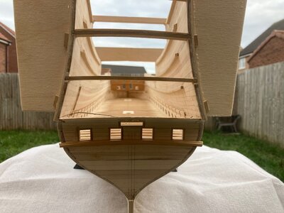
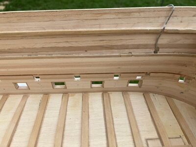
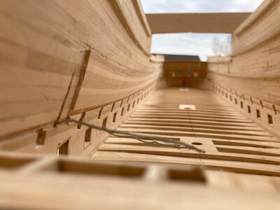
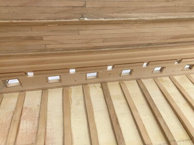


I wonder whether that tiller slot isn’t a bit too wide, given the arc of travel where tiller meets rudder. This jaumier hole would have been a vulnerability for shipping water from following seas, so my guess is that they would have made the opening as small as possible.
At some point I found this on Pinterest, and it has always struck me as a highly plausible framing for the stern:
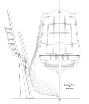
At some point I found this on Pinterest, and it has always struck me as a highly plausible framing for the stern:

I wonder whether that tiller slot isn’t a bit too wide, given the arc of travel where tiller meets rudder. This jaumier hole would have been a vulnerability for shipping water from following seas, so my guess is that they would have made the opening as small as possible.
At some point I found this on Pinterest, and it has always struck me as a highly plausible framing for the stern:
View attachment 327965
I thought that initially Marc, but after drawing the 60 degree fan out from the centreline of where the rudder hinges fall plus adding on half of the tiller ( 3mm/2 )then this is the sweep to the inside face of the transom.I took the 60 Degrees from Goodwin as nothing else I had went into enough detail.
Looking at the above drawing, it would work but with limited rudder throw.The above sketch does have the tip of the rudder penetrating the counter planking??? Why? It does not look right because the tiller would run straight into the deck beams underneath the cabin
Marc, reviewing Michael Saunier's work in this area, it looks like there is negligible projection of the sternpost in this area and the rudder is almost hard up to the transom.This would move the fulcrum closer reducing the width of the necessary slot.Food for thought
That’s interesting - I’m going to go look at my pics of Michel’s models.Marc, reviewing Michael Saunier's work in this area, it looks like there is negligible projection of the sternpost in this area and the rudder is almost hard up to the transom.This would move the fulcrum closer reducing the width of the necessary slot.Food for thought
Also, admittedly, the drawing I posted does seem to have the rudder tip penetrate the counter planking. That is a problem.
I see what you mean about Michel’s sternpost. Unfortunately, I don’t have any good pics showing his tiller opening. This drawing I posted above may actually be Michel’s drawing.
This framing may work with the rudder close to the transom.I will draw it out tomorrow.Narrowing the slot is 20 minutes work
I went through three separate logs of Michel's build on the French forum and could not find one image of the finished tiller opening
I went through three separate logs of Michel's build on the French forum and could not find one image of the finished tiller opening

And.......look at your pic of DR in post no.385.Very shallow sternpost and smaller opening clearly visible
Just big enough to hang one of those Toilet brushes out of


Just big enough to hang one of those Toilet brushes out of


Last edited:
Hello ! This drawing is indeed Michel's early work. Nigel, your jaumier hole is too wide, I will post you some pics showing this detail.
Really nice work by the way, it will be a gorgeous model.

Thank you Marc.Yes I found a square on view in Lemineur's book of Dauphin Royal showing a slot the same height as mine but narrower.I will amend the width to suit a shallower stern post that puts the hinges closer to the transom.
Can I tempt you to post pictures of your great work in our scratch build section?
Kind Regards
Nigel
Thanks Nigel, yes if it is of some interest to you of course I will post the progression of my model on this board !Thank you Marc.Yes I found a square on view in Lemineur's book of Dauphin Royal showing a slot the same height as mine but narrower.I will amend the width to suit a shallower stern post that puts the hinges closer to the transom.
Can I tempt you to post pictures of your great work in our scratch build section?
Kind Regards
Nigel


