-

Win a Free Custom Engraved Brass Coin!!!
As a way to introduce our brass coins to the community, we will raffle off a free coin during the month of August. Follow link ABOVE for instructions for entering.
-

PRE-ORDER SHIPS IN SCALE TODAY!
The beloved Ships in Scale Magazine is back and charting a new course for 2026!
Discover new skills, new techniques, and new inspirations in every issue.
NOTE THAT OUR FIRST ISSUE WILL BE JAN/FEB 2026
You are using an out of date browser. It may not display this or other websites correctly.
You should upgrade or use an alternative browser.
You should upgrade or use an alternative browser.
Soleil Royal- Re-engineering Artesania Latina's New Kit by NMBROOK
One of the things I really like about the stock kit is that they do manage to give the headrails a pleasing shape and proportion that are consistent with the times. I also think the sweep of the headrail support timbers is pretty good.
- Joined
- Dec 7, 2022
- Messages
- 170
- Points
- 113

Great work !
ThankyouGreat work !
Yes they sort of reflect practice of the time, Just a couple of things, firstly the deck follows the middle headrail, not the top, don't think at can do much about that. Secondly the aft most support is only 3mm from the bow planking and I wanted to fit a decent anchor bolster but have only 3mm, not sure if I can get away with cranking the frame so the top remains in the same place and the foot moves slightly forward by a few mm?One of the things I really like about the stock kit is that they do manage to give the headrails a pleasing shape and proportion that are consistent with the times. I also think the sweep of the headrail support timbers is pretty good.
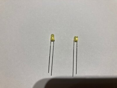
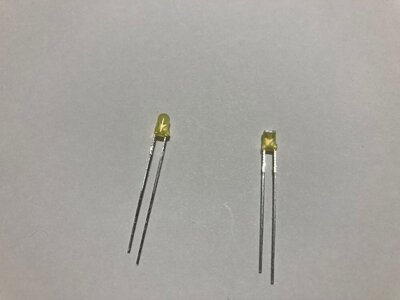
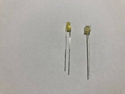
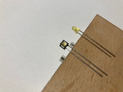
As a post dinner mini project, I decided to try an idea I had for scale working lanterns given the number of LEDs going into the model.Step by step, here is how I did it;
1- Filed the end of a 3mm yellow LED square and then squared the rim around the base, one side already has a flat on to denote the Cathode
2- Bonded a 3mm square piece of 0.5mm styrene to the flat end with medium CA
3- Bonded 0.5mm styrene round to the four corners with medium CA and trimmed the ends flush when set
4- Painted the Lantern "case" with Tamiya XF84 Dark Iron.
Success, I have a lantern that is 4mm x 4mm x 4mm. At 1/65, that is close enough for me.
Now just to repeat over 100 times
Kind Regards
Nigel


It is not the worst thing, if the gratings have to follow the middle headrail. This is a compromise that my revised headrail design also forced me to.Yes they sort of reflect practice of the time, Just a couple of things, firstly the deck follows the middle headrail, not the top, don't think at can do much about that. Secondly the aft most support is only 3mm from the bow planking and I wanted to fit a decent anchor bolster but have only 3mm, not sure if I can get away with cranking the frame so the top remains in the same place and the foot moves slightly forward by a few mm?
As for the aft supporting timber - might it be possible to backfill the slot in the upper knee and then re-slot to move the whole timber forward 1MM, for 4MM clearance for the bolster? I realize this may cause alignment problems with the aft pilasters on the headrails, but that profile can also be cheated forward via a profiling process of addition and subtraction. The outboard faces get covered with lyres, anyway, and you can always paint the inboard face of the headrails.
Genius idea with the lanterns, btw!
One word: Genius.As a post dinner mini project, I decided to try an idea I had for scale working lanterns given the number of LEDs going into the model.Step by step, here is how I did it;
1- Filed the end of a 3mm yellow LED square and then squared the rim around the base, one side already has a flat on to denote the Cathode
2- Bonded a 3mm square piece of 0.5mm styrene to the flat end with medium CA
3- Bonded 0.5mm styrene round to the four corners with medium CA and trimmed the ends flush when set
4- Painted the Lantern "case" with Tamiya XF84 Dark Iron.
Success, I have a lantern that is 4mm x 4mm x 4mm. At 1/65, that is close enough for me.
Now just to repeat over 100 times
Kind Regards
Nigel
View attachment 348260View attachment 348261View attachment 348262View attachment 348263
Thanks Guys
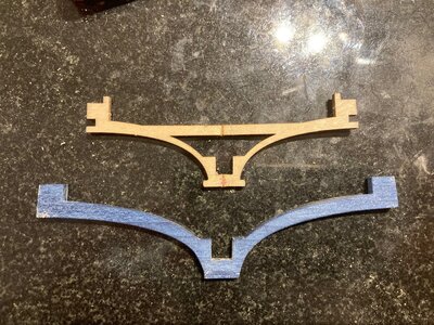
Marc I have gone with moving the aft most support forward 3mm and cranking the support 3mm and the next support 2mm forward with 2mm crank and 1mm on the second support.This means the spacings where the supports contact the frame will all be 19mm and the contact points of the handrail remain 20mm as in the kit so all should match the Pillasters on the headrail.The headrail is the one of the few stock kit parts I am retaining.
Work is now progressing as I have got my head around what I am doing.
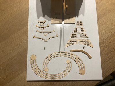
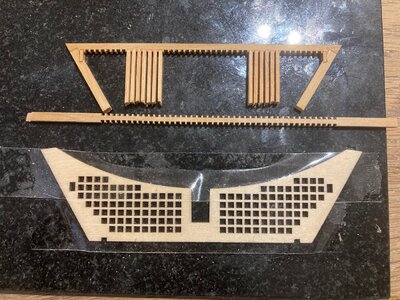
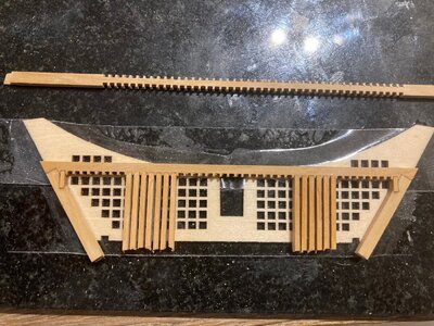
I have started to make replacements for the beak grated decks using the kit items as templates.These are being made from boxwood and I am cutting the notches on the Proxxon mill.All the ends in the pic will be trimmed to length prior to fitting the next transverse beam.
The kit headrail supports are being modified as above, I cut 3/4 of the way through the centreline and set the piece on a flat surface and add medium CA into the cut to retain the crank shape.The piece is then covered on all faces with blue veneer.
Kind Regards
Nigel


Aaaaaah! I wasn’t understanding what you meant by “crank,” but now I get it. Yeah, that alteration will not be perceptible and will definitely allow the bolster clearances you need in order for the whole thing to appear deliberate. The head gratings are a huge upgrade.
Last edited:
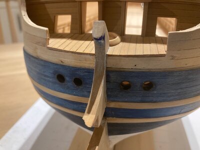
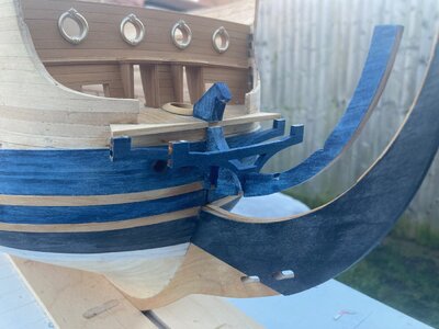
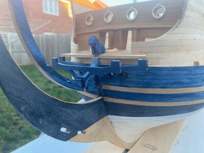
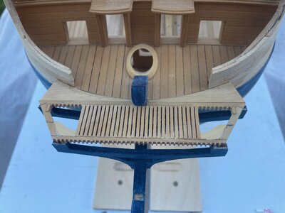
Further progress has been made on the stem.I have repaired the break and covered these sections in veneer.The first two rail supports are in and clad in veneer.I have placed the first section of grated deck ( construction still ongoing) so you get the idea how this all goes together
Kind Regards
Nigel

Kind Regards
Nigel


Like pieces of a puzzle! Super-clean cladding.
Hi All
As one of my New Years resolutions, I have promised myself to finish some long outstanding models.The fact that my workshop is baltic at the moment and I have some sinus irritation from two weeks of working with CA, I am taking a short break from this model.I am revisiting my Hasegawa 1/350 Akagi which has been in safe storage for several years and is well under construction. You will find me loitering in the plastic section for the time being as I am posting a log covering completion of the model
Kind Regards
Nigel
Feel better my friend - ‘hope to see you back at her soon enough.
Feel better my friend - ‘hope to see you back at her soon enough.
Thanks Marc, I am not ill as such, just can't stop having bouts of sneezing. I will have a break from extreme CA use before I develop an allergy.
Kind Regards
Nigel
Amazing work Nigel, i hope you stop sneezing soon, so we can enjoy this build further.
I am a big fan of your work - Very good work btw
Nigel.
Just catching up as always superb work....
Just catching up as always superb work....
- Joined
- Dec 31, 2022
- Messages
- 145
- Points
- 113

Beautiful work!


