-

Win a Free Custom Engraved Brass Coin!!!
As a way to introduce our brass coins to the community, we will raffle off a free coin during the month of August. Follow link ABOVE for instructions for entering.
-

PRE-ORDER SHIPS IN SCALE TODAY!
The beloved Ships in Scale Magazine is back and charting a new course for 2026!
Discover new skills, new techniques, and new inspirations in every issue.
NOTE THAT OUR FIRST ISSUE WILL BE JAN/FEB 2026
You are using an out of date browser. It may not display this or other websites correctly.
You should upgrade or use an alternative browser.
You should upgrade or use an alternative browser.
Soleil Royal- Re-engineering Artesania Latina's New Kit by NMBROOK
Fantastic scratch work as always, Nigel! I found this picture to be helpful as a newbie when trying to learn all the nautical terms for the deck support structure.
View attachment 398869
Thankyou Kurt
I did not use the correct terms as the beam layout is fictional. French design is very different to your picture and also different to my layout.If I had followed what is correct, I would have timbers running the length of the model running right through the centres of my "viewing windows"
So, you'll be placing gun carriages and beams simultaneously, as you work your way aft?
That is the plan Marc. Plus hanging Knees, dummy frame rider extensions and lighting! Oh and all the ironwork plus Main Capstan, further hatches and Rowlock, pause for breath now
 . You get the idea, when I reach the stern, the main gun deck will be done
Super work Nigel! I especially your crisp clean edges on the inner works openings. How do you achieve such clean edges.
Thanks Ken, sharp Scalpel blades and lots of em. I use possibly 5 types and buy each in boxes of 100 at a time
I don't have hundreds of razor knife blades, but I re-sharpen them often on a sharpening stone. (I'm too cheap to buy lots of blades.) However, once re-sharpened, the behavior of the knife blade as it cuts is different. It is no longer as sharp as a new blade so you cannot push it through material as easily, but if you drag the edge across the wood, it cuts like a micro-saw, and cuts well, albeit with a bit more friction.Thanks Ken, sharp Scalpel blades and lots of em. I use possibly 5 types and buy each in boxes of 100 at a time
Last edited:
With no drawings or internal layout of the original, an element of educated guesswork and "winging it" are required.
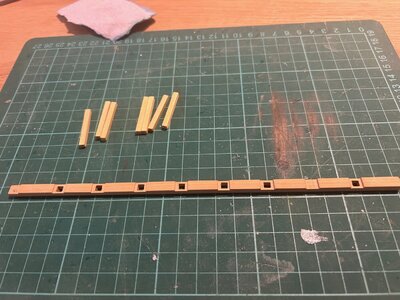
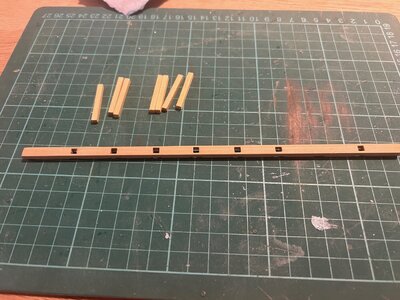
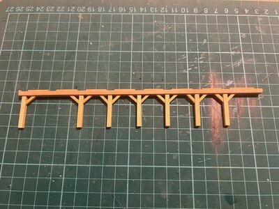
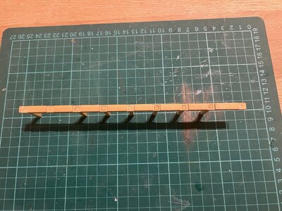
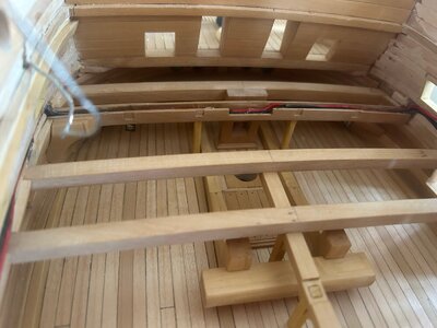
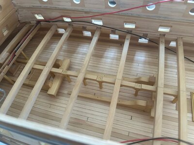
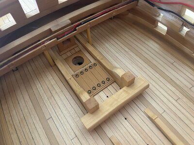
Twin support posts did not work around the Hawse bits so I have opted for central supports with a beam that sits under the deck beams on the ships centreline. This runs from foremast to the first Capstan position. Whilst there is no Capstan on this deck, the shaft from the one above passes through the deck above and into the main deck acting like an axle.
The beam was notched to take the bottom of the deck beams and mortices milled to take the uprights. The beam is slightly curved to match the deck sheer. The cutting mat squares help in ensuring the posts are vertical as the beam rises 5mm over it's length to suit the deck sheer.
The posts are overlong to be trimmed to suit the sheer of the deck and heights of the beams above.


What do you have for morticing, Nigel? Can you show us a picture of you morticing tools? I have a small Lindley jog boring machine from 1964 that is made to drill precise holes for tooling, but doubles as a light mill. Making very small square holes in things is something I have to do with a drill and needle files by hand, and it's hard to be precise using that method.With no drawings or internal layout of the original, an element of educated guesswork and "winging it" are required.
Twin support posts did not work around the Hawse bits so I have opted for central supports with a beam that sits under the deck beams on the ships centreline. This runs from foremast to the first Capstan position. Whilst there is no Capstan on this deck, the shaft from the one above passes through the deck above and into the main deck acting like an axle.
The beam was notched to take the bottom of the deck beams and mortices milled to take the uprights. The beam is slightly curved to match the deck sheer. The cutting mat squares help in ensuring the posts are vertical as the beam rises 5mm over it's length to suit the deck sheer.
The posts are overlong to be trimmed to suit the sheer of the deck and heights of the beams above.
View attachment 399096View attachment 399097View attachment 399098View attachment 399099
What do you have for morticing, Nigel? Can you show us a picture of you morticing tools? I have a small Lindley jog boring machine from 1964 that is made to drill precise holes for tooling, but doubles as a light mill. Making very small square holes in things is something I have to do with a drill and needle files by hand, and it's hard to be precise using that method.
I just used the MF70 mill with a 1mm cutter. The radiuses are removed with a small triangular file, not a square one, you won't get sharp corners with one of those
So you do finish them by hand also. The teeth on square files are beveled off a tiny bit, so yeah... you have to use the triangular file.I just used the MF70 mill with a 1mm cutter. The radiuses are removed with a small triangular file, not a square one, you won't get sharp corners with one of those
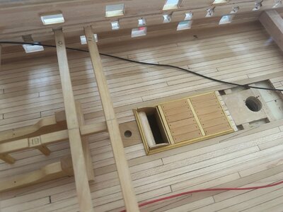
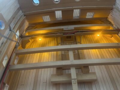
Internal work is trickling along. Initial wiring installed and hidden inside the deck beam. The wires will be glued into the channel I have left in the hull sides as I work backwards installing beams and wiring lanterns. The foremost two are installed and I show a picture of them illuminated which is MUCH brighter than reality.
I have also fitted another set of hatches and the forward one that the anchor cables run through. The top curve is yet to plank.The deck beams and central support structure are merely placed and will come back out again several times. The pivot for the Capstan extension from the deck above has also been inset into the deck.
I have also fitted another set of hatches and the forward one that the anchor cables run through. The top curve is yet to plank.The deck beams and central support structure are merely placed and will come back out again several times. The pivot for the Capstan extension from the deck above has also been inset into the deck.


Excellent work Nigel.
Without going through your build log in its entirety, can you tell me how you achieved the semi transparent blue stain on the planking please ?
I wish to replicate that effect on my current build.
Without going through your build log in its entirety, can you tell me how you achieved the semi transparent blue stain on the planking please ?
I wish to replicate that effect on my current build.
Thankyou Brian
It is an off the shelf dyed veneer. I purchase it from a company called Original Marquetry in the UK
It is an off the shelf dyed veneer. I purchase it from a company called Original Marquetry in the UK
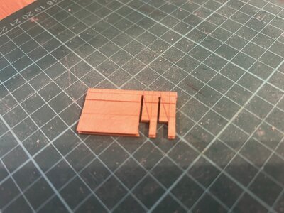
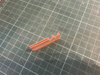
Carrying on with the pump details. The pump tubes are dowel drilled through on the lathe with the outlet holes added with my MF70.
I used the MF70 to shape a boxwood blank that will form six pivot support timbers (there are two pumps next to the mizzen).The iron bands are blackened brass strip cut from sheet.
Next step is a coat of varnish before fitting in the model. The pump handles will be fitted later after the deck has received it's final coat of varnish
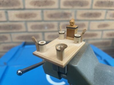
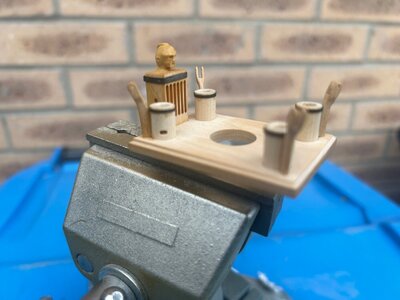


Super impressive detailing. The Turk is pleased, despite his stoicism.
Thanks Marc and he has been stuck in a drawer for ages 

He's probably parched. The non-functioning pumps account for his expression...Thanks Marc and he has been stuck in a drawer for ages
I rehydrated him a few hours ago Paul, but with a coat of varnish
The subassembly has been given a coat of matt poly and is now bonded into the deck. I have started added eyebolts and rings to the hatches. As well as gluing the eyelets (Caldercraft photo etched ) into holes in the timber, I have applied a diluted dot of Mig Ultra glue to the ring to stop it rattling about. I will also varnish over these when I apply the final coat to further lock them in position.
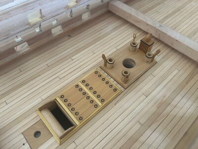
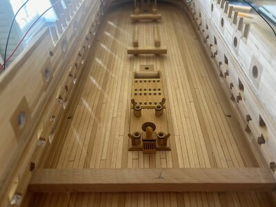


Thank you for orienting the rings perfectly. You and I would be mates if we lived near one anotherThe subassembly has been given a coat of matt poly and is now bonded into the deck. I have started added eyebolts and rings to the hatches. As well as gluing the eyelets (Caldercraft photo etched ) into holes in the timber, I have applied a diluted dot of Mig Ultra glue to the ring to stop it rattling about. I will also varnish over these when I apply the final coat to further lock them in position.
View attachment 401719View attachment 401720View attachment 401721
I don't doubt it Paul It costs nothing and minimal extra effort to align them perfectly
 They will move about if not glued and look poor if all over the shop.
Just this deck will take an age, I am absolutely Anal when it comes to detail. I haven't decided if that is a good or bad trait In the background, I am working on the ends of the breaching ropes, two cannons complete so far
 It takes me half an hours work on each end to exactly replicate the detail Uwe showed earlier in my log
 There are actually three seperate bindings per end, apologies for the crappy iPhone pics
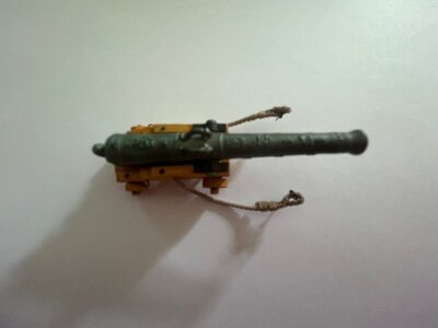
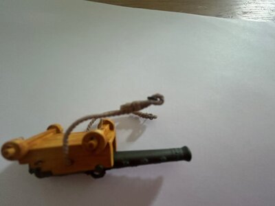
Just this deck will take an age, I am absolutely Anal when it comes to detail. I haven't decided if that is a good or bad trait
 In the background, I am working on the ends of the breaching ropes, two cannons complete so far
 It takes me half an hours work on each end to exactly replicate the detail Uwe showed earlier in my log


