• Beginning at 5:00AM PST (13:00 UTC) on Friday February 14th, all services in the Los Angeles, California, USA Data Center will be offline to perform a Data Center Migration. Due to the nature of this migration, we anticipate up to 24 hours of downtime to safely complete this work. Please be patient during this time and thank you for being a valuable member of our community.

Syren 1803 1:64 Model Shipways

Hi Roger. That is good to know and great work .As you say the sharing of these ideas is a really good way to learn new techniques. Aye aye Captain....so funny can’t stop laughing ROTF.All the best with your next surgery.
Thanks Grant. This treenail concept using small hollow needle-like devices, with and without a drill press, has been around since at least 2013. Most searches refer back to the methods of a modeller from Russia. I don’t know who it was but he/she deserves the credit and praise.

Now I just have to see if I have the patience to do the same.
 
Thanks Grant. This treenail concept using small hollow needle-like devices, with and without a drill press, has been around since at least 2013. Most searches refer back to the methods of a modeller from Russia. I don’t know who it was but he/she deserves the credit and praise.
Hello Roger, Yoy are correct, Making treenails using the blunt needle was first introduced and invented, perhaps by Aleksandr Dobrenko (he suddenly passed away in July 2019). Alexander was not only an extremely accomplished modeller but also was a key player in the Model Shipbuilding Guild of StPetersburg and the Russian Shipmodeling Guilds as a whole.
 
Hello Roger, Yoy are correct, Making treenails using the blunt needle was first introduced and invented, perhaps by Aleksandr Dobrenko (he suddenly passed away in July 2019). Alexander was not only an extremely accomplished modeller but also was a key player in the Model Shipbuilding Guild of StPetersburg and the Russian Shipmodeling Guilds as a whole.
Thanks for the information Jim. It’s great to know about and give recognition to Alexander.
 
Here is a link to a student/protégé of Mr. Dobrenko where he uses this technique:

 
Last edited:
Just before the holidays I received a package of Swiss pear and Alaskan yellow cedar in the mail. The billets are mostly 14” x 4” of various thicknesses. I am pleased with the quality of the wood. The pear will be for the deck and the cedar for the inner bulwarks.

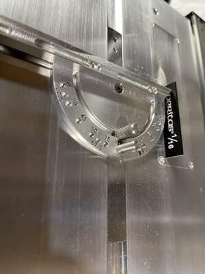
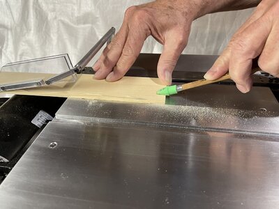
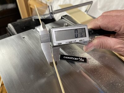
I have a Byrnes table saw and was thinking about how I could make an accurate measuring jig when I start cutting the yellow cedar (1/8” thick) into 1/16” strips. There are various methods in articles and on-line showing different types of jigs, some homemade, some commercial. But the miter gauge with the adjustable extension bar provides an easy solution.

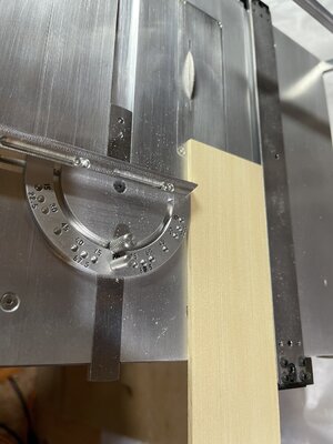
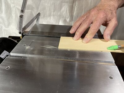
Firstly, and importantly, I do not use the miter gauge and fence at the same time. I unscrewed the little adjustment screws on the extension bar slightly. I then used a 1/16” set-up block as a spacer between the slitting blade and the adjustable extension bar. Adjusted the bar against the set-up block, tightened the screws and then moved the miter gauge towards the front of the table. Placing a billet in position I moved the fence so the edges of the wood lay between and against the fence and extension bar. Tightened the fence, removed the miter gauge from the table and started my first cut. The result was an accurate 1/16” strip as shown.

Each cut now requires just repeating the miter gauge and fence process, as in the first cut, but that just takes seconds.

(By the way, the blade guard was moved out of the way for the photographs only).

91455F5F-1CAA-4987-A9E3-D06FFC41E4A0.jpegD234341C-3072-42B1-A98B-D9E0EFAA0E9A.jpeg34478A03-EC27-4BB9-86C4-FB3F5CD76374.jpeg81E2F803-219E-4D6C-BA86-FB09F9D3F874.jpeg97A2DFD9-6B7A-47DA-8214-8897CF716B8C.jpeg
 
This is a clever idea, Roger. don't have to reinvent the bike. What is the source of your timbers purchase? Did they cut billets to your size or just based on avalability?
 
Thanks Jim, it works well for repetitive cuts. Then for a different thickness it’s just a matter of adjusting the extension bar.

I sourced the wood from Joseph Volpe in New Jersey. The sizes are listed on his site milled to size, he also says if you need a custom size to contact him. He is very helpful and the order was filled quickly.

 
Wo Roger, that Byrnes certainly looks like the number to have. Unfortunately though, that is an acquisition that will have to wait for the not foreseeable future. :)
 
Ok, back at it with some frustrating time spent sorting out the stern area. I don’t feel I have moved forward much but, to me, solving issues is part of the learning process.

For the stern inboard planks I cut some strips of alaskan yellow cedar and airbrushed them with a primer then a Vallejo red. The red is an exact match to the Model Expo Bulwarks Red paint. I then cut, fitted and glued the planks to the stern inboard. That limits any sanding overall but there are some parts to level out. In hindsight I should have fitted the planks unpainted. That way I could have ensured the planks were more level adjacent to each other, then brush painted later.

8F9E612B-C658-4501-93FB-3340D5A51AA9.jpeg

I then turned to the fashion pieces and so started a confusing few days. There are three fashion pieces, upper, middle and lower. The lower one cuts into the upper wale. The manual says fit the wales first, then notch out upper wale. I decided to fit the fashion pieces first because I had already airbrushed the wales black. I didn’t want to have crushed basswood edges. The instruction then say to add a second layer but only to the mid and lower fashion pieces.

5471387A-C0EE-491B-A741-FC218BD5C321.jpeg

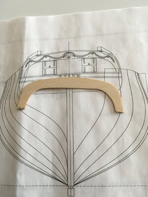
The confusing part is the wings of the transom and the laser cut second transom layer. Once the mid and lower fashion pieces are built up the transom wings need to be sanded back quite a bit. The upper fashion piece is one piece only. This will then allow the cap rail to be moulded over the stern. The lower part of the cap rail then joins to the built up middle fashion piece. The problem is that wonderful looking curve in the transom gets lost and becomes more straight when cut back port and stb’d. So I went back to the plans and see that the second transom layer is substantially smaller. I definitely have to cut it back :confused:. So much so I wonder how the cast decorative carvings will look when it all comes together.

E65FA296-AC99-4746-A04B-39D186087AE3.jpeg

Anyway, onward with the knife and sander after the wales are completed. By the way I decided to stain the upper strakes and did not, as you can see, treenail for various reasons.
 
Hi Roger. It is good to see you back at the bench - and as far things going slowly - that is OK, so don't fret about it. I agree with you on the transom - cutting it back by the amount that seems to be required may have an adverse effect on the transom decorations. My only advice would be to look at the lesser of the two evils. The transom has to fit properly, so I would first work towards getting that in place as that I believe should be the priority. Then, if the decorations don't fit, we can always make adjustments later.
 
Thanks for your input Heinrich. Remembering the ship scale is 1:64 and most supplied wood for the hull and stern area is 1/16”. There might be another option that will keep that transom curve intact.

I wonder if going against the build instructions I double the layer of the upper fashion piece (now becomes 1/8” thick). That will take up and fill much of that overhang of the transom wings. Then adjust the mid and lower by using three layers (goes from 1/8” to, say, less than 3/16”). I’d still have to have that middle piece thick enough to allow the cap rail to still fit flush. That in turn may need a thinner cap rail, which is at present 1/16”.

Then the issue is the practicality of a ship from 1803 having thicker fashion pieces. Top becomes around 8” real scale, mid and lower about 12” or less. I cannot find a reference that will provide me that answer.

My continued thanks to you and everyone for the help, advice and likes.
 
Just a little update, which forces me to keep on track and be self accountable.

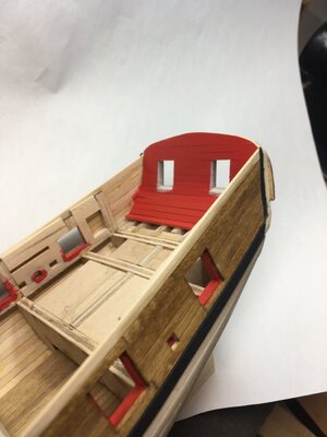
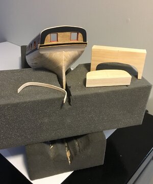
I spent some time trying to sort out the construction method for the ass end (am I allowed to say that?). I tried to keep the original transom curve each side by increasing the thickness of the fashion pieces but ended up staying with the excellent instructions. It means the transom straightens out somewhat but I think it looks ok. Like a lot of other Syren builders I found I had to build up and adjust that area in preparation for the mid and lower wales, and aft cap rail.

I used the kit supplied second upper transom piece (black in my photo) but broke it sanding the edges before fitting it. It’s very flimsy but I had made a cardboard template just in case so made another piece. I stained that one, broke the darn thing again and made another. Then looking at Novastorms Syren build I found really liked his interpretive painted black piece. It adds something to that area. Since no-one knows what the aft end of the Syren really looked like I decided to follow suit.

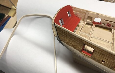
Then it was aft cap rail time. I had already made another of my pine wooden templates (I think I was a shoe maker in a past life :D) and then soaked a cap piece that bent reasonably well but, to me, it was not good enough. I broke that accidentally so made another. That one turned out well so that is what I will use. No wonder making this model takes me forever, my excuse anyway.

The mouldings that I had I carved are now fitted as you can see, I made a couple more as a backup. (I now wear a carving glove in case you are reading this @Jimsky Jim ).

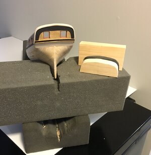
That’s it for now, the cap rail is only temporarily fitted in the photo. I have to shape it and round the edges tomorrow. By the way my foamy dry-dock shown in the images is recycled from a computer packaging box. It’s quite soft on the model and holds the model well as I rotate, turn and invert it.

I am starting to wonder if I write too much in these posts but maybe it will help other new modellers get some ideas, as I have from others.

As always thanks for comments, advice, likes and just looking in on my build.
FB2698BD-1E0E-4C54-9A46-9E438B1CB900.jpeg3B4B7966-ED80-4810-873F-F76529C4587C.jpeg
 
Last edited:
That stern and cap railing look too sexy for words! Thumbsup

3B4B7966-ED80-4810-873F-F76529C4587C.jpg

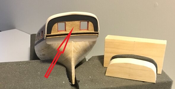
Tell me Roger, what is going to happen to the area that I have marked with the red arrow? Does this still get planked, painted or finished in any other way?

With regards to your writing - that is exactly what prospective builders of this model need - so don't you change one thing! Thumbsup
 
Thanks Heinrich, your words are always valuable. A great question about that “bare” area of the transom and a really good observation. I have been pondering that for weeks and I’m open for suggestions.

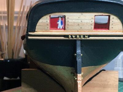
The black second layer of the upper transom is now glued and fixed in place, with a combination of PVA and CA. After getting the shape and proportions just right I really don’t want to remove it. I didn’t plank that area very early on but now wished I had. It doesn’t look right.

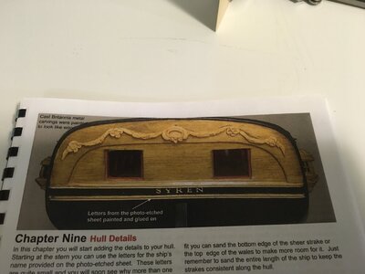
My thinking at the time was planking it would have increased the total stern width too much but I have seen it done and it must have worked out ok. The designer left it as is (see below) but I think it was a function of his construction design.

So my options now are:
1. It’s already stained so leave as is and hope the additional fixtures and fittings detract from that area. Personally I’ll never be happy with that.
2. Paint it all black, which I saw on one build. Maybe a little overpowering.
3. That black upper transom piece is 1/32” thick. I have some very fine veneer at 3/128”. I could cut scale width planks, stain and fit. That would still give me the raised lip between the black piece and planks, but only just. I also have to then consider the additional thickness of the aft gun ports.
5. Challenge my Byrnes saw capabilities and try to cut down to 1/64” for planks. Might be a fun project tomorrow.
6. Throw it out there for opinions :) .

Thanks.

Photo from Chuck’s manual:

9906260B-C5D4-4ED3-A396-E82411F8FF45.jpeg

Veneers I have in stock:

E78ABF6D-7CA0-4ED5-AB76-490080FAB336.jpeg
 
Last edited:
Hi Roger.

When it comes to the Syren - my go-to-build has always been that of @NovaStorm. Here is what he has done. At least it's an option to consider. Start warming up that Byrnes. :)

View attachment 287825
Challenge accepted….
……… and completed ;)

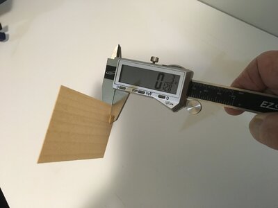
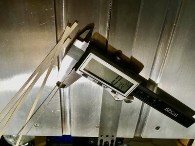
My respect for the Byrnes table saw just went sky high. I used a #99 slitting blade, with a previously cut zero clearance insert and the low profile ripping fence. The result is a few lengths of 1/64” thick basswood. Now for the revised transom planking.

C20A3E4D-5B12-4D38-A888-A3BF4D19CA07.jpeg
 
Last edited:
Now that is how it should be done!!!! Thumbs-UpThumbs-UpThumbs-UpI am sure that the Byrnes is excellent, but its operator also has to know what he is doing. With that transom planked, you are going to have a picture perfect stern! I am so glad that you found my suggestion helpful.
 
Now that is how it should be done!!!! Thumbs-UpThumbs-UpThumbs-UpI am sure that the Byrnes is excellent, but its operator also has to know what he is doing. With that transom planked, you are going to have a picture perfect stern! I am so glad that you found my suggestion helpful.
Thanks for your vote of confidence Heinrich, your suggestions are always more than helpful.
 
Back
Top