-

SUBSCRIBE TO SHIPS IN SCALE TODAY!
The beloved Ships in Scale Magazine is back and charting a new course for 2026!
Discover new skills, new techniques, and new inspirations in every issue.
NOTE THAT OUR NEXT ISSUE WILL BE July/August 2026 -

Win a Free Custom Engraved Brass Coin!!!
As a way to introduce our brass coins to the community, we will raffle off a free coin during the month of August. Follow link ABOVE for instructions for entering.
You are using an out of date browser. It may not display this or other websites correctly.
You should upgrade or use an alternative browser.
You should upgrade or use an alternative browser.
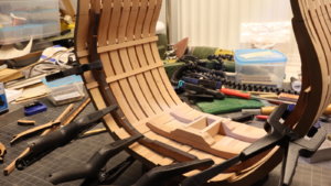
USS BONHOMME RICHARD - POF - Cross Section in Pear - 1:48 - by Uwe


Installation of the thick stuff planking. Due to the curvature of the frames, the planks had to be chamfered / beveled

The counter blocks have the same curvature, so that the three planks are pressed against the frames

I also started with the preparation of the riders - the different elements are very good shown in the building log of John (neptune)

Many thanks for the interest .... to be continued ......
The counter blocks have the same curvature, so that the three planks are pressed against the frames
I also started with the preparation of the riders - the different elements are very good shown in the building log of John (neptune)
Many thanks for the interest .... to be continued ......

Hi Uwe,
looks pretty good.
Karl
looks pretty good.
Karl
Many Thanks Karl and all others for the comments and likes - hope to restart the building soonHi Uwe,
looks pretty good.
Karl
Hallo - I am back again - means back in the workshop and I was able to make some sawdust.
After weeks concentrating on other private things (puppy dog, daughter in 1.st class, job and preparation for christmas.....) I am really happy to be able to "work" for some hours.....
First step was to finalize the three thick stuff planks on both sides and to pre-prepare the riders and the "normal" planks

still some sanding necessary on the visible areas - the contact area with the planking will be finally adjusted when the planking is fixed to the frames


Planking is fixed and the riders are temporary layed - now the can be adjusted to meet the contour of the planking.

I used for the first planks on the left and the right side of the keelson in a different thickness (not according the kit, but according Boudriot.
Also because of this half mm difference the bottom contour of the riders have to be adjusted (on the left hand you can slightly see this already.)


I hope to show you the next progress soon....... to be continued .....
After weeks concentrating on other private things (puppy dog, daughter in 1.st class, job and preparation for christmas.....) I am really happy to be able to "work" for some hours.....
First step was to finalize the three thick stuff planks on both sides and to pre-prepare the riders and the "normal" planks
still some sanding necessary on the visible areas - the contact area with the planking will be finally adjusted when the planking is fixed to the frames
Planking is fixed and the riders are temporary layed - now the can be adjusted to meet the contour of the planking.
I used for the first planks on the left and the right side of the keelson in a different thickness (not according the kit, but according Boudriot.
Also because of this half mm difference the bottom contour of the riders have to be adjusted (on the left hand you can slightly see this already.)
I hope to show you the next progress soon....... to be continued .....

Good to see you back building the cross section Uwe, looking great, I also picked up on that first plank next to the keel being thicker, but I just went with the kit planking layout, I also noticed that he only has 7 planks between the keel and the thick stuff but in the kit there are 8, anyway enjoy your build, i look forward to following,
best regards John.
best regards John.

Good to see the French soldier is back on the deck.
Or did you cut out an american for this build?
Or did you cut out an american for this build?

Love to see your work! And, the more I see the cross sectional models, the more I want to build one.
thank Uwek!
thank Uwek!
He is an American in the French uniform...Good to see the French soldier is back on the deck.
Or did you cut out an american for this build?

Good to see the French soldier is back on the deck.
Or did you cut out an american for this build?
The USS Bonhomme Richard was originally a french EastIndiaman merchant ship named Duc De Duras and was built in Lorient (France). So the surveyor is definitely French, inspecting the work in the shipyard in Lorient.He is an American in the French uniform...
Thanks for your interest
Many Thanks for the comments and also the likes - much appreciated 
After some short time today in the workshop a small update.
The two riders were adjusted now to the form of the planking and fit very well (in my opinion) - most of this area will be not visible in the final model


and one rider was prepared with some brass "bolts" of 0,8mm diameter, to imitate the connection between rider and frame

to be continued ......
After some short time today in the workshop a small update.
The two riders were adjusted now to the form of the planking and fit very well (in my opinion) - most of this area will be not visible in the final model
and one rider was prepared with some brass "bolts" of 0,8mm diameter, to imitate the connection between rider and frame
to be continued ......
Last edited:

Looks very good. To fit in details like this is hell in my opinion. But i don´t have practice with such kind of work.
Many thanks for the comments and all the likes
Some smaller progress was possible today....... still dry fit. I like to wait until the last moment, before I fix something finally with glue


I am also often waiting with final fixing, due to the fact, that I check most of the parts also, if they fit with the other elements which will be also installed later in this area, f.e. her with the octagonal pump-tube (i do not know the correct english term) - I made one example and checked where it will be located


To get the octagonal form I used this tool to fix the square form during sanding - so I got the correct angles

Some smaller progress was possible today....... still dry fit. I like to wait until the last moment, before I fix something finally with glue
I am also often waiting with final fixing, due to the fact, that I check most of the parts also, if they fit with the other elements which will be also installed later in this area, f.e. her with the octagonal pump-tube (i do not know the correct english term) - I made one example and checked where it will be located
To get the octagonal form I used this tool to fix the square form during sanding - so I got the correct angles
Hi Uwe,the pear wood looking awesome in this kit,where did you buy that tool?
One of the next steps is the installation of the lower deck clamps of the different heights

Within the kit Unicorn models is also supplying some small jigs / small rulers for every different deck level, where the location of the different beams are marked.
You can see with pencil marks, the location of one beam is already prepared with a small chisel (one the right). A very clever idea by the manufacturer.

here all location for deck 3 are prepared


and the obligatory dry-fit of the beams (only at the beam in front the laser char is already removed)

Here the elements of the main rider, which is over more or less the complete height of the hull....... once more a first check how it fits all together, before I start to prepare and finalize this one

Many Thanks for your interest ..... more to come in the next days - Holidays, so I have the chance to be some time in the workshop


")
Within the kit Unicorn models is also supplying some small jigs / small rulers for every different deck level, where the location of the different beams are marked.
You can see with pencil marks, the location of one beam is already prepared with a small chisel (one the right). A very clever idea by the manufacturer.
here all location for deck 3 are prepared
and the obligatory dry-fit of the beams (only at the beam in front the laser char is already removed)
Here the elements of the main rider, which is over more or less the complete height of the hull....... once more a first check how it fits all together, before I start to prepare and finalize this one
Many Thanks for your interest ..... more to come in the next days - Holidays, so I have the chance to be some time in the workshop
Hallo Zoly,Hi Uwe,the pear wood looking awesome in this kit,where did you buy that tool?
OHHHHH Yes - the quality of the timber in the kit is really the best I found in a kit
Because of such positive experience I am recommending every time to the manufacturer to use for the kits good or very good timber.
It is making a kit more expensive, but it is worth every additional cent you pay for it.
Tool? Do you mean the metal block for sanding the octagonal form?
Some 10 years ago I bought a complete used "metal workshop" from a steam engine modeler - this was part of it. (in addition lathe, drill, mill etc. and a lot of accessoires)
I do not know the correct terminus for these elements, but they are keeping the square in exact 45° - Maybe somebody else can tell us the correct name / term?
I found the german term for it: "Bohr-Prisma" or "Spann-Prisma"Hallo Zoly,
OHHHHH Yes - the quality of the timber in the kit is really the best I found in a kit
Because of such positive experience I am recommending every time to the manufacturer to use for the kits good or very good timber.
It is making a kit more expensive, but it is worth every additional cent you pay for it.
Tool? Do you mean the metal block for sanding the octagonal form?
Some 10 years ago I bought a complete used "metal workshop" from a steam engine modeler - this was part of it. (in addition lathe, drill, mill etc. and a lot of accessoires)
I do not know the correct terminus for these elements, but they are keeping the square in exact 45° - Maybe somebody else can tell us the correct name / term?
Look these photos:
I do not know the correct terminus for these elements, but they are keeping the square in exact 45° - Maybe somebody else can tell us the correct name / term?
Happy New Year, friends!! This tool called V-BLOCKHi Uwe,the pear wood looking awesome in this kit,where did you buy that tool?

V-block - Wikipedia
Thank you guys!!
Some small update of the today´s progress
I worked and finalized the other deck clamps and worked on the main rider, not completely finished with sanding (f.e. the side areas),but it fits very well inside the hull.
The simulation of the bolts is already finished, once more brass nails with 0,8mm diameter


I made the timber of the rider a little bit wet, to get an impression of the final finish and to see the "bolts" better


Many Thanks for your interest ..... hope to see you soon here in my building log
I worked and finalized the other deck clamps and worked on the main rider, not completely finished with sanding (f.e. the side areas),but it fits very well inside the hull.
The simulation of the bolts is already finished, once more brass nails with 0,8mm diameter
I made the timber of the rider a little bit wet, to get an impression of the final finish and to see the "bolts" better
Many Thanks for your interest ..... hope to see you soon here in my building log