USS Constitution MS2040

Mixing up my own paint. Combo of green and white. I can give the details later on the mix.

So, I am almost finished with the rivets, but I could not resist doing some painting. Ok, so the black inboard sides of the Gun Ports are "simulated" black using a graphic program only to show the "contrast' that will be present when painting those Gun Port inside walls with Black. The Hull Black actually wraps around INTO the sides of the Gun Ports. The Green is ONLY for the Bulwark facing inside.

In case you are wondering, the Deck Planking Strips that lay right beside the Waterways will be painted "before" they are glued down. Then the remaining Deck Planking can be laid down without painting until later. I am trying to decide if I want to do nibbing or not. Never done it before. I do not want to mess that up.

Also, to me personally, I did not sand the Bulwarks glass smooth as this is not reality as we all know that over the years and time, planks have been replaced and if you look at the real ship, it is not going to be glass smooth, but you will see imperfections. If it were sanded glass smooth, then you would loose alot of the texture of each plank butted up against the other.

With the layer of paint the rivets looks great, Donnie.
Regards from another riveter, Peter
 
Mixing up my own paint. Combo of green and white. I can give the details later on the mix.

So, I am almost finished with the rivets, but I could not resist doing some painting. Ok, so the black inboard sides of the Gun Ports are "simulated" black using a graphic program only to show the "contrast' that will be present when painting those Gun Port inside walls with Black. The Hull Black actually wraps around INTO the sides of the Gun Ports. The Green is ONLY for the Bulwark facing inside.

In case you are wondering, the Deck Planking Strips that lay right beside the Waterways will be painted "before" they are glued down. Then the remaining Deck Planking can be laid down without painting until later. I am trying to decide if I want to do nibbing or not. Never done it before. I do not want to mess that up.
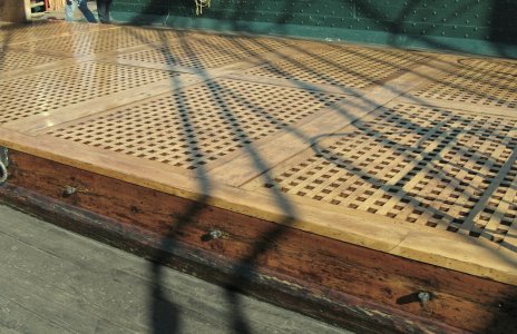
Also, to me personally, I did not sand the Bulwarks glass smooth as this is not reality as we all know that over the years and time, planks have been replaced and if you look at the real ship, it is not going to be glass smooth, but you will see imperfections. If it were sanded glass smooth, then you would loose alot of the texture of each plank butted up against the other.

Late to the ball as usual. Donnie! The rivets are a masterstroke! Thank you for the complete tutorial!

Blessings. Peace. Gratitude.
Chuck
 
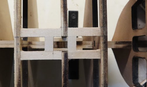
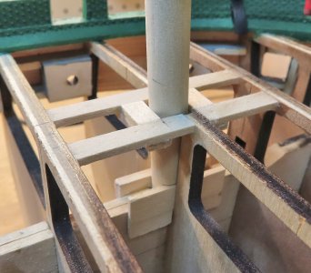
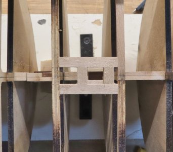
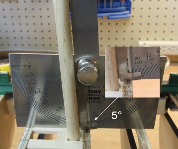
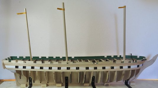
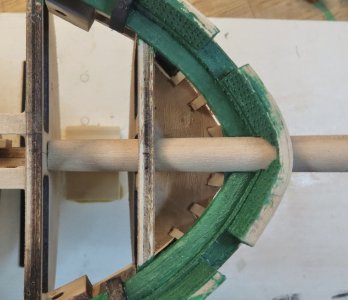
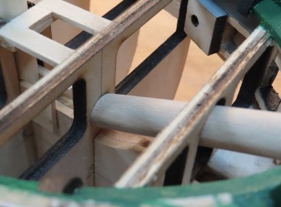
I only have a few more rivets to go. I decided to take a break from Rivets and work on Mast Partners. They were built up as per the plans.


FOREMAST 3° RAKE:


mast-partners-fore-01.jpg

mast-partners-fore-02.jpg

mast-partners-fore-03.jpg


---------------------------------------------------------------------------------------------------------------


MAIN MAST 3.5° RAKE


mast-partners-main-04.jpg

mast-partners-main-05.jpg


---------------------------------------------------------------------------------------------------------------


MIZZEN MAST 5° RAKE


mast-partners-mizzen-01.jpg

mast-partners-mizzen-02.jpg


---------------------------------------------------------------------------------------------------------------

FINAL FULL HULL VIEW WITH MAST.


full-mast-view-01.jpg

full-mast-view-02.jpg


I decided to change over to MicroMark's Battery Operated powered screwdriver with added chuck. The main problem with the chuck is that the opening of the chuck is slightly larger than the shaft of the driver, therefore the chuck wobbles slightly. To overcome this, I wrapped the shaft of the driver with one lap of tin foil which filled in the gap. Now, the drill bit and chuck runs true (well, lets say a lot better). Ideally, the tip of the electric screwdriver really needs to have a "screw on thread type" that will keep ALL attachments true. The motor and shaft do run quite very true (no run-out - i.e. wobbling). However, in MM's defense, I would say that after-all, the driver is really intended to drive screws and not drill bits. But, with a little modification, it gets the job done well.

So, this process is not really that bad. What you see here is about 5 hours of work. No glue has been used, just the pressure of the holes are keeping the rivets in place. They should not come out unless you or someone takes the time to pull them out.


just remember that wood moves. so as wood dries, it shrinks and your rivets may come loose. just a thought......
 
did you try fitting in the bowsprit? I had a heck of a time getting it through the hole that I had to make in the hull for it.
 
Well, the thing is Jack S. . . .
Even I get stuck with the same mindset - that other ships are done better than mine - which can lead to much frustration and disappointment. Believe me, I have done a lot of rework that I did not mention here on the forum. The MS Constitution is complicated because you must rely on the plans. That booklet (manual) that came with it is not good.


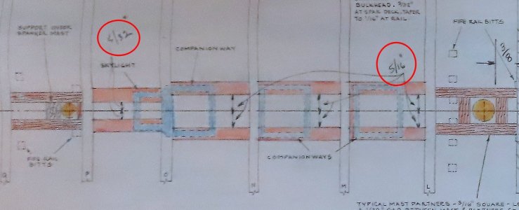
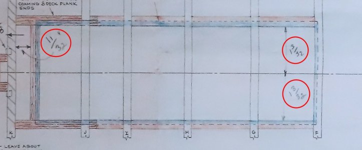
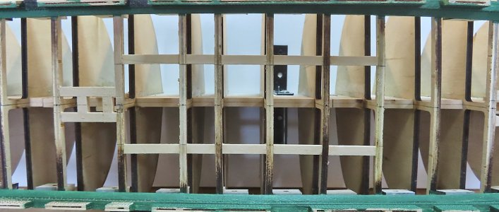
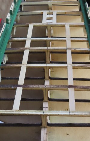
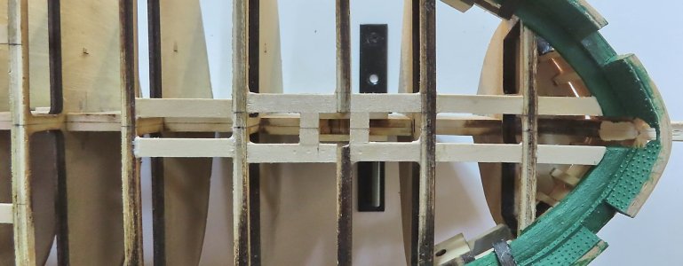
So, before I finish off the rivets, I might go ahead and lay out the framing for the Hatches. If I were not relying on Bob Hunt's Practicum (at this point), I would be lost as the plans (sheet 2) just do not show enough info.

Therefore, I decided to rough out the measurements and use color as a go-by. The orange is the framing, and the blue should be the actual coamings/hatches.

NOTE: I will be using 1/4" x 3/32" for all framing. That is the reason why some of the framing that I have penciled in looks a little wider. The point is not to focus on the width of framing, but to take VERY close note of the dimensions BETWEEN the Framings. Looking closer, you will see all the dimensions shown.

Therefore, the dimensions are listed here for your convenience:

All measurements are shown as an X/Y BULKHEAD component - these are the bulkheads where the measurements are taken from the CENTER-LINE on each side !!!
MEASURE ON EACH SIDE OF CENTER-LINE

f.e, Between Bulkhead A and B the measurement will be 7/32" on one side and 7/32" on the other side. Draw a line extending from A to B.

A/B 7/32"
D/E 5/32"
F/G 1-3/32"
G/H 1-3/32"
H/I 1-3/32"
I/J 1-3/32"
J/K 1-3/32"
L/M 5/16"
M/N 5/16"
N/O 5/16"
O/P 5/32"


hatch-framing-01.jpg


hatch-framing-closeup-01.jpghatch-framing-closeup-02.jpghatch-framing-closeup-03.jpg
 
Last edited:
It didn't help when I had to rip off the deck because I had ruined it with the paint that I put on it, but overall that only set me back about 1 hour in total so not too bad. If I don't like how something looks, I will not hesitate to redo. For example I have been working on the cheek knees and I must have redone them at least 3 times because I didn't like how they looked. I have one finished and now moving on to the other one.
But overall, I would say it is still fun. If it wasn't I probably wouldn't be doing this build.
 
I am building my MS Conny with a fully equipped gun deck which meant that I have to leave the spar deck open enough to view the gun deck. Therefore, I built the main hatch with half of the hatches open to enhance viewing. However, this became a can of worms because the kit's main hatch design does not match the actual ship, especially the 1927 version from which the MS kit is based. See posts #932 - #934. Hopefully, this inconsistency does not mess up your build.

Jon
 
I look at all these build logs and I'm astonished by the high quality of work accomplished. I can only imagine how they built the reals ships with mostly hand tools & saws and employing wenches to lift the heavy pieces and such. It's amazing to me that they actually float when they're done. P. J. O'Rourke opined in his book "Holiday's in Hell" that sometimes 'hand-made' means ten thumbs. :D Hat's off to you guys that build these great ships in miniature! The precision of creating these models is every bit as incredible as the real ships. In fact, more so because of the downsizing involved. Way more patience and attention to detail than I possess.
 
Yes, Jim it takes a certain amount of dedication and drive to maintain a project like this to the end.

Well, I shied away from planking the lower deck and adding real guns instead of the fake ones. The Bulkheads are made in a way with the additional cutouts that would allow a builder to easily modify that lower deck with planking and real guns if they want to - so since I tend to be intrinsically lazy at times, I chose the least path of resistance :):):)

I have learned that once a decision is made, you have to follow it all the way through. Same with the Rivets, I knew that once I started, I could not go back, and it would ruin the inside bulwarks of where I decided to stop and try to patch up the tiny holes. So, I began with installing 2000 Rivets !!!! However, adding the Rivets was not so bad after all. Being armed with a "very slow RPM pencil drill/screwdriver loaded with a #77 bit" and a jig to help with spacing, it did not take that long to do.
 
#1 NOTE: Before anything is done, I highly suggest that when you are installing the Bulkheads, you not only make sure they are as square as you can get them to the keel, but now is the time to install scrap wood spacers between each bulkhead, making 100% sure you have equal measurements on the PORT and STARBOARD sides all the way down the hull.
I opted not to do that, thinking inaccuracies would not creep in. I was wrong. Way later in the build, when I started to add the Hatch Coamings Framing, I noticed that maybe two of my Bulkheads had a skew in them. I was able to correct most of this, but now I wish I had done the spacers. Balsa Fillers are not necessary, as those blocks can very much interfere with the building process, but scrap like 1/8 x 1/4 inch spacers will do fine.
 
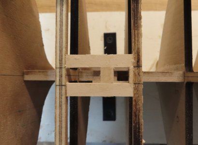
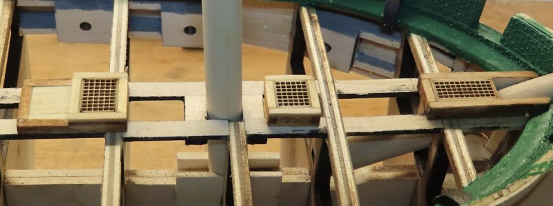
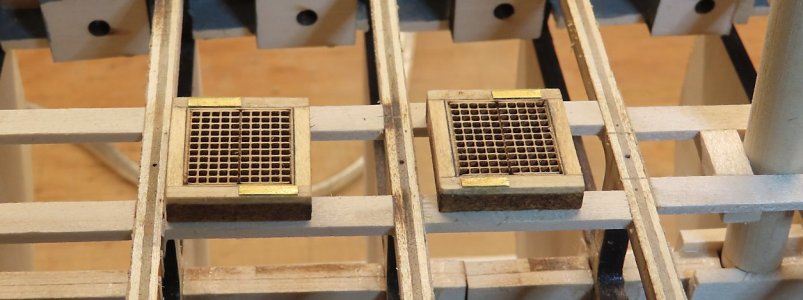
I am going to depart completely away from the Practicum I am following and (even the plans) as I wish to have more of a modern look of the hatches. Therefore, I am building up my own frame - but - keeping in spec with the height which is 7/16" in height.
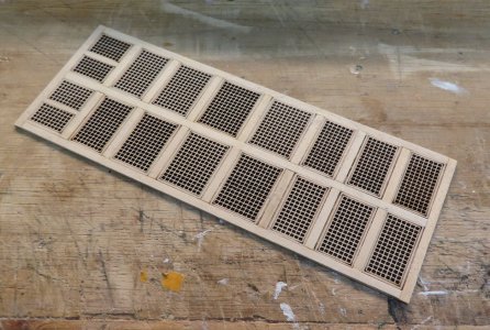
I removed all the grates from the lazer cut piece and made my own frame.

Here are the sizes I used:
5/64 x 1/8 for the grating trim. (as this trim is the exact thickness of the grates).
1/8 x 1/4 for the frame
1/16 x 1/16 for the hatch supporting cleats.


hatch-framing-09.jpg

hatch-framing-10.jpg

hatch-framing-11.jpg


I used RED OAK stain and GOLDEN OAK for the project. I think it looks very close to the real thing. Nothing has been glued down yet.

hatch-framing-12.jpg

hatch-framing-13.jpg
 
I am going to depart completely away from the Practicum I am following and (even the plans) as I wish to have more of a modern look of the hatches. Therefore, I am building up my own frame - but - keeping in spec with the height which is 7/16" in height.
I removed all the grates from the lazer cut piece and made my own frame.

Here are the sizes I used:
5/64 x 1/8 for the grating trim. (as this trim is the exact thickness of the grates).
1/8 x 1/4 for the frame
1/16 x 1/16 for the hatch supporting cleats.


I used RED OAK stain and GOLDEN OAK for the project. I think it looks very close to the real thing. Nothing has been glued down yet.
they look identical.great job
 
I am going to depart completely away from the Practicum I am following and (even the plans) as I wish to have more of a modern look of the hatches. Therefore, I am building up my own frame - but - keeping in spec with the height which is 7/16" in height.
I removed all the grates from the lazer cut piece and made my own frame.

Here are the sizes I used:
5/64 x 1/8 for the grating trim. (as this trim is the exact thickness of the grates).
1/8 x 1/4 for the frame
1/16 x 1/16 for the hatch supporting cleats.


I used RED OAK stain and GOLDEN OAK for the project. I think it looks very close to the real thing. Nothing has been glued down yet.
Shazam! Wow Donnie! I have been loving your precision, but this is next level stuff!

Blessings.
Chuck
 
Back
Top