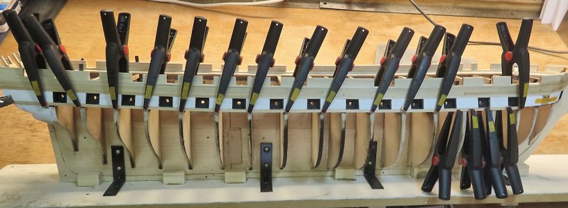
Looking great !
-

Win a Free Custom Engraved Brass Coin!!!
As a way to introduce our brass coins to the community, we will raffle off a free coin during the month of August. Follow link ABOVE for instructions for entering.
-

PRE-ORDER SHIPS IN SCALE TODAY!
The beloved Ships in Scale Magazine is back and charting a new course for 2026!
Discover new skills, new techniques, and new inspirations in every issue.
NOTE THAT OUR FIRST ISSUE WILL BE JAN/FEB 2026
You are using an out of date browser. It may not display this or other websites correctly.
You should upgrade or use an alternative browser.
You should upgrade or use an alternative browser.
- Joined
- Oct 9, 2020
- Messages
- 2,228
- Points
- 488

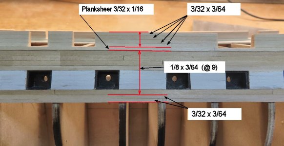
I have had my share of misshaps too on this build and perhaps the worst was that I had to replank the entire deck. I made a mess with the stain and it looked like crap. So now I am undecided about whether I should stain the deck or not, even though I found a way to do it so that it looks good.Well, I was wondering why things were going along so smoothly - I screwed up MAJOR big time - but I am not so far ahead that it can not be corrected. I deleted all my post showing the installations of the port sill framing. I was supposed to use 1/8" spacing from the lower edge of the planksheer to the bottom edge of the upper sill. I did not use this spacing. I used 3/32 --- arggggg. So, what that means is that all the gun port frames will have to be moved DOWN some.
by some, I mean at least about 1/4" or more.
So, I had just finished all the planking around the gun ports, when I realized that something was not adding up. On the frikken plans, they only give the THICKNESS of 3/64 and not the WIDTH of the planks - this is a major error as far as I am concerned.
Time to get out the water (to soften glue) and start moving gun port frames downward. Crap !!!! Well, I guess it is a good thing I caught it now.
- Joined
- Oct 9, 2020
- Messages
- 2,228
- Points
- 488

i like your idea of painting the white parts off the ship. It makes things look a lot neater.
- Joined
- Aug 6, 2024
- Messages
- 45
- Points
- 48

I have not watched any of your build logs before, but find this one excellent. Question though, do you start any sub assembly building while you are working on
the hull?
the hull?
Hi Clipper,
No, I just follow through with the task at hand. (and thank you for your compliments).
This is the latest:
Rivets:
Bought from Hobbylinc
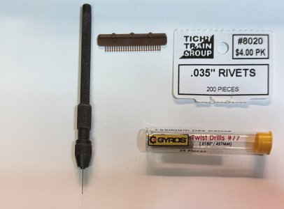
.035 Rivets (200) -- HO Scale Model Train Part #8020 Note: the .035 is the Rivet "head" diameter and not the shaft part of it. DO NOT use a .035 Drill Bit.
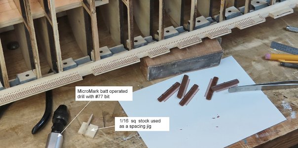
Use at least a #77 bit as shown in last photo. Lastly, if you decide to do this, cut the Rivets off the sprue using an exacto knife and cut them off at an ANGLE - this will produce a sharp edge to help go into the holes.
Drill Bits:
Bought from Amazon
Pin Vise:
Bought from MicroMark

 micromark.com
No, I just follow through with the task at hand. (and thank you for your compliments).
This is the latest:
Rivets:
Bought from Hobbylinc
Hobbylinc
Hobbylinc.com carries over 70,000 hobby products at savings up to 60% including plastic model kits, model trains and railroads, model rockets, arts and crafts, paint, tools, supplies and more. Call to order toll-free at 1-888-327-9673
www.hobbylinc.com
Use at least a #77 bit as shown in last photo. Lastly, if you decide to do this, cut the Rivets off the sprue using an exacto knife and cut them off at an ANGLE - this will produce a sharp edge to help go into the holes.
Drill Bits:
Bought from Amazon
Pin Vise:
Bought from MicroMark

Pin Vise 4‑Pc Set | Machinist Hand Drill Bit Kit | Micro-Mark
This durable 4‑pc pin vise kit holds wire/drill bits from 0–3/16″. Features knurled steel handles, corrosion-resistant finish, ideal for model and hobby tasks.
 micromark.com
Very nice to see this kind of rivets and to show how you install them, Donnie.Hi Clipper,
No, I just follow through with the task at hand. (and thank you for your compliments).
This is the latest:
Rivets:
Bought from Hobbylinc
.035 Rivets (200) -- HO Scale Model Train Part #8020 Note: the .035 is the Rivet "head" diameter and not the shaft part of it. DO NOT use a .035 Drill Bit.Hobbylinc
Hobbylinc.com carries over 70,000 hobby products at savings up to 60% including plastic model kits, model trains and railroads, model rockets, arts and crafts, paint, tools, supplies and more. Call to order toll-free at 1-888-327-9673www.hobbylinc.com
Use at least a #77 bit as shown in last photo. Lastly, if you decide to do this, cut the Rivets off the sprue using an exacto knife and cut them off at an ANGLE - this will produce a sharp edge to help go into the holes.
Drill Bits:
Bought from Amazon
Pin Vise:
Bought from MicroMark

Pin Vise 4‑Pc Set | Machinist Hand Drill Bit Kit | Micro-Mark
This durable 4‑pc pin vise kit holds wire/drill bits from 0–3/16″. Features knurled steel handles, corrosion-resistant finish, ideal for model and hobby tasks.micromark.com
Thanks from another ‘riveter’, Peter
I decided to change over to MicroMark's Battery Operated powered screwdriver with added chuck. The main problem with the chuck is that the opening of the chuck is slightly larger than the shaft of the driver, therefore the chuck wobbles slightly. To overcome this, I wrapped the shaft of the driver with one lap of tin foil which filled in the gap. Now, the drill bit and chuck runs true (well, lets say a lot better). Ideally, the tip of the electric screwdriver really needs to have a "screw on thread type" that will keep ALL attachments true. The motor and shaft do run quite very true (no run-out - i.e. wobbling). However, in MM's defense, I would say that after-all, the driver is really intended to drive screws and not drill bits. But, with a little modification, it gets the job done well.
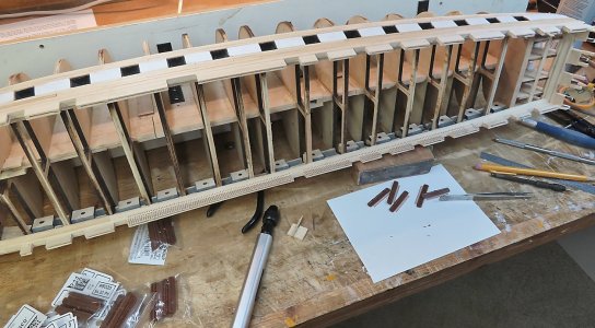
So, this process is not really that bad. What you see here is about 5 hours of work. No glue has been used, just the pressure of the holes are keeping the rivets in place. They should not come out unless you or someone takes the time to pull them out.

 micromark.com

 micromark.com
So, this process is not really that bad. What you see here is about 5 hours of work. No glue has been used, just the pressure of the holes are keeping the rivets in place. They should not come out unless you or someone takes the time to pull them out.

Quality Tools & Supplies for Hobbys, DIY & Crafts – Micro-Mark Tools
We offer precision tools and supplies for all your hobby projects. Shop high-quality tools for model making, woodworking, painting, crafting and more!
 micromark.com

Drill Chuck For Precision Powered Screwdrivers
Buy our Drill Chuck For Precision Powered Screwdrivers for only $19.95
 micromark.com
- Joined
- Oct 9, 2020
- Messages
- 2,228
- Points
- 488

looks good. I decided not to include rivets but I may change my mind.I decided to change over to MicroMark's Battery Operated powered screwdriver with added chuck. The main problem with the chuck is that the opening of the chuck is slightly larger than the shaft of the driver, therefore the chuck wobbles slightly. To overcome this, I wrapped the shaft of the driver with one lap of tin foil which filled in the gap. Now, the drill bit and chuck runs true (well, lets say a lot better). Ideally, the tip of the electric screwdriver really needs to have a "screw on thread type" that will keep ALL attachments true. The motor and shaft do run quite very true (no run-out - i.e. wobbling). However, in MM's defense, I would say that after-all, the driver is really intended to drive screws and not drill bits. But, with a little modification, it gets the job done well.
So, this process is not really that bad. What you see here is about 5 hours of work. No glue has been used, just the pressure of the holes are keeping the rivets in place. They should not come out unless you or someone takes the time to pull them out.

Quality Tools & Supplies for Hobbys, DIY & Crafts – Micro-Mark Tools
We offer precision tools and supplies for all your hobby projects. Shop high-quality tools for model making, woodworking, painting, crafting and more!micromark.com

Drill Chuck For Precision Powered Screwdrivers
Buy our Drill Chuck For Precision Powered Screwdrivers for only $19.95micromark.com
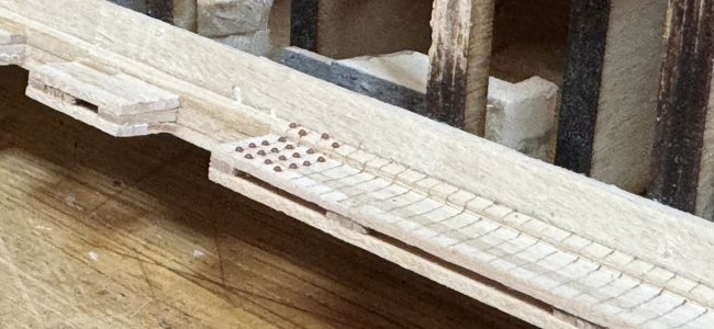
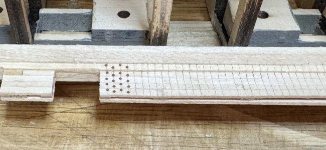
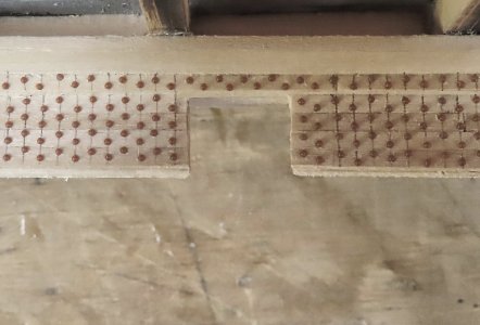
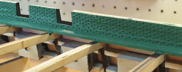
This is a closeup of how I managed to install the rivets in an orderly fashion keeping the flow of alternating even through the Planksheer under the Cannon ports. This is important to keep a consistency.
Unfortunately, I did not catch this early and at least I only have one area that I did not follow this rule. But, I doubt very seriously after all is said and done, I will be able to find it. Much less anyone else.
I am not sure if I mentioned this, but the Rivets are spaced at 1/16 inch (imperial measurements).
Shifting my work to the Stern now.
This picture (actual drawing of measurements) shows the result of getting things lined up for the 3 openings below the 'upper gun ports'. The center port is the only one that will be in a vertical alignment with the upper gun port. Here is a drawing of my results. There should be enough measurements to deduct reasoning. The remaining images show the build up.
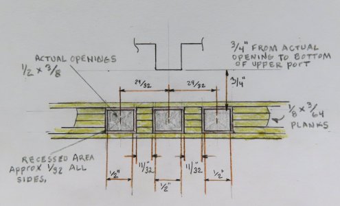
So, this is the beginning:
The scrap piece is used as an ALIGNMENT - the scrap piece is secured at the BOTTOM of the Transom Extension pieces. As I recall, all the measurements will be taken from this reference point. I also found out that the HEIGHT of the Extension pieces needed to have about a 1/32 to 1/16 scrap added to each side (eventually). for now, just use the bottom of the extension as they come from the kit as is.
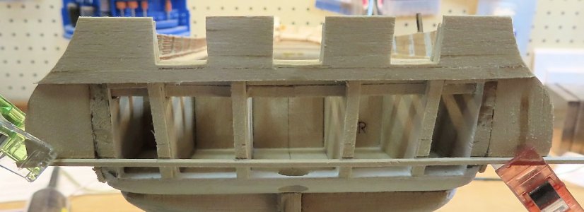
Here are the TICK MARKS laying out the position of the openings. You will notice that I have already added the scrap pieces to extend the HEIGHT of the Transom extension pieces.
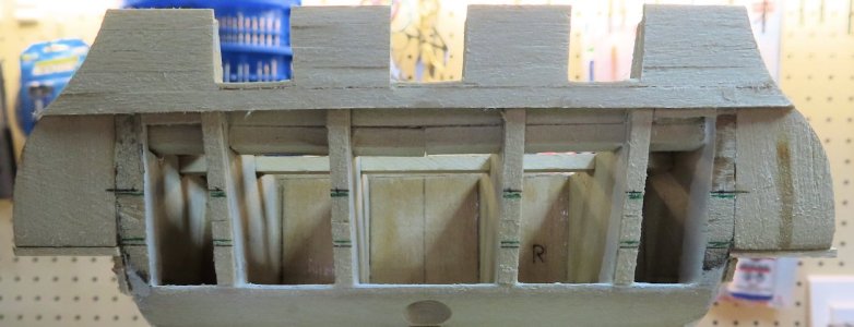
Start adding 1/8 x 1/4 pieces to "frame" the openings.
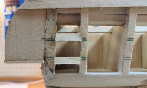
I found later on that I had to make some slight adjustments to the port framing (as we all know that wood is not exactly a perfect science). Adjustments as much as + / - 1/32" was needed on some framing to line up with the planking. This is all due to the nature that the stern has CURVATURE and is NOT a flat surface.
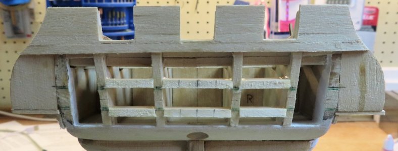
As I noted, you might have to make some slight adjustments to the frame versus the planking due to curvature. The OBJECTIVE is to make sure you have at least 1/32 inches as a recess for the LIDS to lay into.
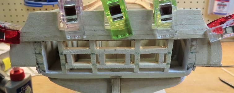
And this is the final result of your achievements.
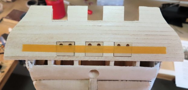
This picture (actual drawing of measurements) shows the result of getting things lined up for the 3 openings below the 'upper gun ports'. The center port is the only one that will be in a vertical alignment with the upper gun port. Here is a drawing of my results. There should be enough measurements to deduct reasoning. The remaining images show the build up.

So, this is the beginning:
The scrap piece is used as an ALIGNMENT - the scrap piece is secured at the BOTTOM of the Transom Extension pieces. As I recall, all the measurements will be taken from this reference point. I also found out that the HEIGHT of the Extension pieces needed to have about a 1/32 to 1/16 scrap added to each side (eventually). for now, just use the bottom of the extension as they come from the kit as is.

Here are the TICK MARKS laying out the position of the openings. You will notice that I have already added the scrap pieces to extend the HEIGHT of the Transom extension pieces.

Start adding 1/8 x 1/4 pieces to "frame" the openings.

I found later on that I had to make some slight adjustments to the port framing (as we all know that wood is not exactly a perfect science). Adjustments as much as + / - 1/32" was needed on some framing to line up with the planking. This is all due to the nature that the stern has CURVATURE and is NOT a flat surface.

As I noted, you might have to make some slight adjustments to the frame versus the planking due to curvature. The OBJECTIVE is to make sure you have at least 1/32 inches as a recess for the LIDS to lay into.

And this is the final result of your achievements.

- Joined
- Oct 9, 2020
- Messages
- 2,228
- Points
- 488

that's what mine looks like. I had originally lined up all three ports but then realized that it was incorrect so I had to redo. I have been doing a lot of redo on this model. At times it is quite discouraging, but I want to finish it so I do what is required...Shifting my work to the Stern now.
This picture (actual drawing of measurements) shows the result of getting things lined up for the 3 openings below the 'upper gun ports'. The center port is the only one that will be in a vertical alignment with the upper gun port. Here is a drawing of my results. There should be enough measurements to deduct reasoning. The remaining images show the build up.
View attachment 502800
So, this is the beginning:
The scrap piece is used as an ALIGNMENT - the scrap piece is secured at the BOTTOM of the Transom Extension pieces. As I recall, all the measurements will be taken from this reference point. I also found out that the HEIGHT of the Extension pieces needed to have about a 1/32 to 1/16 scrap added to each side (eventually). for now, just use the bottom of the extension as they come from the kit as is.
View attachment 502806
Here are the TICK MARKS laying out the position of the openings. You will notice that I have already added the scrap pieces to extend the HEIGHT of the Transom extension pieces.
View attachment 502807
Start adding 1/8 x 1/4 pieces to "frame" the openings.
View attachment 502808
I found later on that I had to make some slight adjustments to the port framing (as we all know that wood is not exactly a perfect science). Adjustments as much as + / - 1/32" was needed on some framing to line up with the planking. This is all due to the nature that the stern has CURVATURE and is NOT a flat surface.
View attachment 502809
As I noted, you might have to make some slight adjustments to the frame versus the planking due to curvature. The OBJECTIVE is to make sure you have at least 1/32 inches as a recess for the LIDS to lay into.
View attachment 502810
And this is the final result of your achievements.
View attachment 502811
Well, I have done a lot of re-doing too. Putting down wrong-size planks. Re-doing port framing, etc.
Nice, detailed work on the stern, Donnie. As Jon knows, I have been extensively following Jon's Constitution build on Model Ship World, as I have my own Model Shipways Constitution kit on the shelf waiting for my current ship's completion. And I, too, recently saw both your build log here, Donnie, as well as @Jack Sparrow 's build log, so have been taking notes on both of yours, as well. Excellent work, fellas!Just discovered your build log. You have a wealth of other builders to learn from or teach as the case may be out there, so I look forward to your updates.
Jon
What make is your drill press, I love it.I have finished the Bearding Line and am now starting the Glue-up. For the Sternpost, I am using brass Rods as Pins to secure it down due to its irregular shape, which makes it difficult to get it to stay in place.
Mixing up my own paint. Combo of green and white. I can give the details later on the mix.
So, I am almost finished with the rivets, but I could not resist doing some painting. Ok, so the black inboard sides of the Gun Ports are "simulated" black using a graphic program only to show the "contrast' that will be present when painting those Gun Port inside walls with Black. The Hull Black actually wraps around INTO the sides of the Gun Ports. The Green is ONLY for the Bulwark facing inside.
In case you are wondering, the Deck Planking Strips that lay right beside the Waterways will be painted "before" they are glued down. Then the remaining Deck Planking can be laid down without painting until later. I am trying to decide if I want to do nibbing or not. Never done it before. I do not want to mess that up.
Also, to me personally, I did not sand the Bulwarks glass smooth as this is not reality as we all know that over the years and time, planks have been replaced and if you look at the real ship, it is not going to be glass smooth, but you will see imperfections. If it were sanded glass smooth, then you would loose alot of the texture of each plank butted up against the other.
Last edited:
As far as I know, the deck planking was not nibbed but tapered. I have not seen any builder nib their planks. Most of the builders didn't even realize they were supposed to be tapered slightly the bow and stern, not that you could see it on the model.
Jon
Jon


