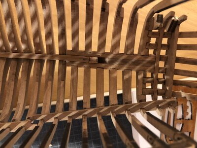
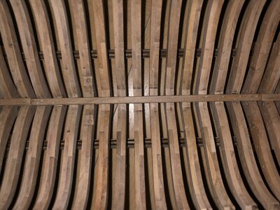
YQ Bluenose by Johan [COMPLETED BUILD]

Hey Dean,
If I would have known what I know today when I ordered the kit, I still would have bought it, I'm really impressed by the plank on frame idea and how stunning she potentially may look, once completed. In itself the pear ís beautiful, no doubt about that.
My current plans are to partially plank the lower deck, with pear, the same with the upper deck. I'm also working on a design to install some internal lightning and there are some more items I want to add or replace. Adding sails is still subject of discussion between the Admiral and me...
Having said that, buying this kit will inherently bring the builder some headache, but still I think it's worth the effort.
Johan
Agreed, it's all about the challenge! Like Peter once said, "if it put itself together, where would be the fun?" ;)
 
Last edited:
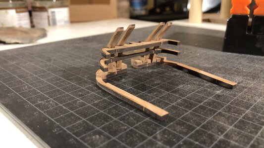
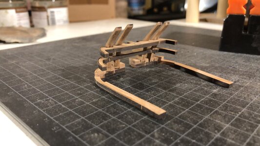
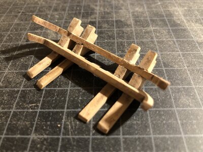
While completing the aftmost frames, I simultaneously started on the transom structure, frames 56 and 58 and parts 51 and 52. After dry fitting these six parts I started to wonder how to approach attaching these parts to frame 55 and the transom. As I mentioned on @Canoe21 's build log, currently I'm very much inclined to turn these parts into a sub-assembly. It means that instead of adding six small parts individually to the build, I install just one, slightly more robust part. The drawback is that I have to make sure all interfaces are matching almost seamlessly and how do you know that works without bonding the sub-assembly first?

Dry fitted frames 55 (on the cutting mat), frame 56 and 57 stacked on top, and parts 51, 52, 52 and again 51 from left to right. The frames have already been filed to fit to the keel/transom or whateveryoumightcallit.
DA3AAED6-44E5-4D7F-8B6E-C0C2E1FA4E00.jpeg
 
The last couple of weeks, after three weeks relaxation on Lanzarote, were spent building frame after frame after frame, cutting, removing char, bonding frame parts, removing some more char, dry fitting, filing some more parts, beveling, inserting toothpicks, sanding, dry fitting. Well you know the drill.

Sunset over the beach at Lanzarote.

AD38E166-1B73-4028-B779-375B932F1C87.jpeg

Finally all the frames have been completed and are now bonded to the keel. During the installation process the keelson fit was continuesly checked, as well as proper seating of the frames to the keel and perpendicularity of the frame with the jig. I also used spacer blocks to maintain the appropriate frame pitches.
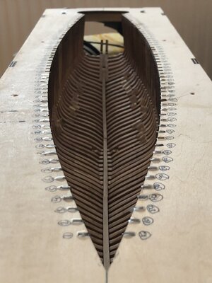
54CCD12A-933F-4535-94CB-2E4CCBCF5EE9.jpeg

During the bonding process I carelessly broke of two of the two transom spiderlegs already installed. Nice going...

Next challenge was the sub-assembly of the last two frames with the spiderlegs, see also my post #202. First remark here is that the lasermarks were ridiculously deep; I could not altogether get rid of these lasermarks. @Peter Voogt said most of the area will be covered, but I know it and now you know as well. Sick

33EE10B2-AD1B-4E1F-B029-89D9D826364E.jpeg

First thing I did after some filing action, prior to beveling, was to perform a dry fit. That went exceptionally well, so confidently I started to bevel all the parts.

Dry fit, prior to beveling:
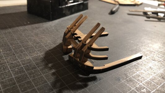
0E6652A9-543D-48C3-8AE7-E45EDFB77DF1.jpeg
FD549BA3-CA00-4329-9A7F-8BD340CA7AB5.jpeg

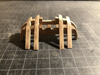
After beveling, again dry fitting.
In the second picture the excessively deep lasermarka can be clearly observed. In my desire to get rid of these marks I went a little overboard. My guess is I'll have to pay the price later.
F8568BC6-968F-42C4-8190-EDEDF1C6A2D2.jpeg33EE10B2-AD1B-4E1F-B029-89D9D826364E.jpeg

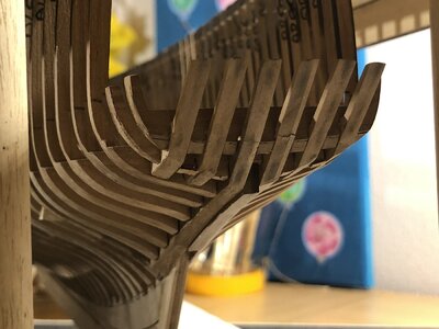
After having finished the sub-assembly, I joined the assembly with frame 55. Here I was met with an unsuspected issue; I did not account for the bonding layer in the two transom parts extending aft of the deadwood. This cost me a lot of time to get it to fit, especially care was taken to stay away from the spiderlegs.
And finally the transom was attached. Obviously "some" touch-up is required, I could/should have done a better job, but here it is.
94D26945-2C99-4EF6-AC81-800E5035CB5D.jpegB430DA7D-48A7-4147-92D7-989C517CFC8F.jpeg

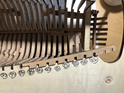
Next on my list to do was the installation of the spacers, parts 24 through 29. The first 5 out of six LH spacers went in without a sweat. Then came around number six. Trying to getting it in position, I found this to be impossible; the notches in the spacers did not match the frame spacing. Initially I suspected a lousy positioning of the frames, but was able to rule that out because these notches do not match with the jig either. In the picture below I matched the notch with the jig at frame 55. At frames 49 and 49 a mismatch occurs of around1.8mm to 2.0mm.
84131170-82AB-4040-8545-F7C59D365E3D.jpeg

First idea was to cut up the spacer into the three different parts:
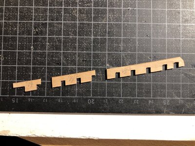
0CBAD2B7-5F75-4065-B33E-8FF98E0F19DC.jpeg

Th picture below shows the dry fit and I didn't like it very much.
By the way, I asked for help from my DBBS collegues and Peter Voogt referred me to his blog where he showed his solution to this issue. Interested? See page 68 of his blog, post 1354.
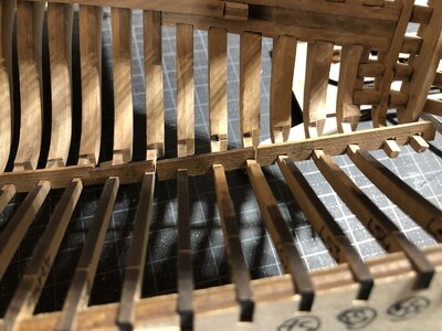
CBEE570E-3613-4399-A44A-692FBEA634FC.jpeg

The next thing I did was to make myself two templates, one LH and one RH and checked those with the hull. Much better:
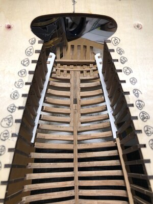
04851FF7-CD0B-483E-9E33-228F1FDF24EA.jpeg

The outlines of these templates have now been transferred to some scrap pieces of wood I kept for you-don't-know-when-you-need-it reasons. Tomorrow I'll find myself sanding and filing and fitting and hopefully I will find myself pleased with the outcome of my labor later tomorrow.
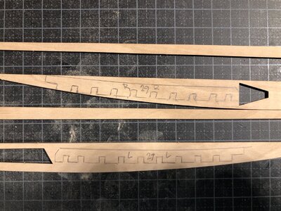
557E3ACD-2ACB-4A59-A8B3-9D4C19AB4E5A.jpeg
 
That’s a lot of work accomplished Johan! Looking great! Those waterway boards are no fun! Keep in mind they should be at the height of final installation when installing the inner frames. Otherwise the spacing could vary depending on height. I literally had to flex a few frames to match the notches! The notch distances will be far more constant than the frames. :(
 
That’s a lot of work accomplished Johan! Looking great! Those waterway boards are no fun! Keep in mind they should be at the height of final installation when installing the inner frames. Otherwise the spacing could vary depending on height. I literally had to flex a few frames to match the notches! The notch distances will be far more constant than the frames. :(
Thanks Dean!
Initially I thought I messed up the frame installation, even though I used the jig and the frame locations on the keel. No amount of frame flexing could get the waterways to fit. Then, after checking the waterways with the frame pitching in the jig, I realized the aft waterways did not and could not match the jig. I am positively surprised you got the waterways in at all, especially so since the mismatch is about .080".
By the way, I've seen this issue in other blogs as well; we're not alone...

I did use a file to open the notch some. I took wood off of the same side on all notches. ;)
 
Hi Johan. We've had a lot of contact about this piece of construction. It takes the necessary perseverance, but eventually it takes shape. It's great that the molds also offer a solution for you to build some parts from scratch to get it right. Dean has explained nice additions in his posts.
Regards, Peter
Yep, it's very nice to be able to discuss those issues with friends who have been there, seen that, done that, in combination with "some" building experience... Invaluable!
 
Hi Johan,

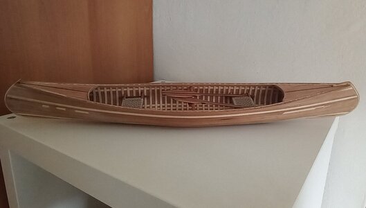
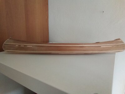
you are finally joining me! I finished my diversion (19 "canoe) and I am attaching pics to you.
IMG_20220318_144230_907.jpg
IMG_20220318_144452_993.jpg

I too had problems entering the waterways, but forcing a little, like Dean, they entered!

Now I take back my BN but I have a question: the waterways must be positioned ABOVE the deck and not below, right? The pic of the white waterways is not from your BN ... Seems to be a Peter's pic ...
 
Hi Johan,

you are finally joining me! I finished my diversion (19 "canoe) and I am attaching pics to you.
View attachment 296872
View attachment 296871

I too had problems entering the waterways, but forcing a little, like Dean, they entered!

Now I take back my BN but I have a question: the waterways must be positioned ABOVE the deck and not below, right? The pic of the white waterways is not from your BN ... Seems to be a Peter's pic ...
What a beautiful model! Thumbs-Up
 
Now I take back my BN but I have a question: the waterways must be positioned ABOVE the deck and not below, right? The pic of the white waterways is not from your BN ... Seems to be a Peter's pic ...
The picture with the white waterways is mine; I made some cardboard models for some new ones I want to make. The cardboard just happened to be white.
Now the question on the vertical position of the waterways; per YQ build instructions they are supposed to go on to of the decksheets/planks. @Peter Voogt used a more sensible approach, the waterways and deckplanks flush with one another. This makes sense, the waterways on top of the deck results in watertraps, thus lots of water on deck not being able to be drained properly. Peter modified the width of the waterways and he also introduced custom made nibbling planks, see his log for more detail: https://shipsofscale.com/sosforums/threads/yuanqing-bluenose-peter-voogt.6566/page-67
If you by any chance have a copy of the Saga of the Great Fishing Schooners, you can find some fine details of the deck supporting structure.
 
Thanks Johan for your answer!
In fact, I believe that YQ's instructions reverse the assembly of the wayerways and deckplank. Otherwise, as you say, the water would not flow properly overboard finding a step ... I will definitely go for the Pater's option by slightly reducing the parts (have you seen how delicate the waterways are?).
Last, no Johan I don't have a copy of the Saga ... I don't think there is an Italian version of It.
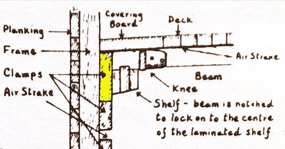
Below a cross section of the deck of the Bluenose. Here the waterway has been referred to as covering board. What's in a name.
The picture is taken from the "Saga".1647623880218.jpeg
 
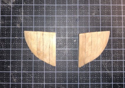
Two different jobs for today: first the shaping of the two bow blocks, second the production of the aft waterways.
The two bow blocks were a first for me; I never dared to shape massive wooden blocks before. The result of this exercise are satisfactory, especially so since these two blocks will be covered almost completely.

00C1C742-B12B-4130-A9BF-5C9055ECC3EF.jpeg

The second job for today was the manufacturing of the two aft waterways.
This turned out to be a failure. First I inadvertently used the wrong wood, probably due to selecting the material in artificial light. Secondly, I used the Dremel sanding drum for the contour of the part and a disk for the notches. This turned out to be a bad choice of tools.

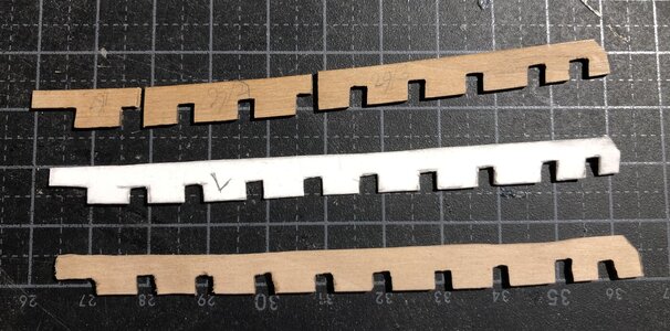
The picture below, from to bottom:
- The cut up original waterway, part 29,
- The template for a new waterway,
- The first try at a new part. Not conforming to specification; disposition: scrap.

C0A52B9D-385B-403F-BEAF-6994E07B2D60.jpeg

Luckily I found some pieces of the correct material and for the next try I'm opting to use a figure saw to get a more conforming waterway. Fingers crossed.
 
Two different jobs for today: first the shaping of the two bow blocks, second the production of the aft waterways.
The two bow blocks were a first for me; I never dared to shape massive wooden blocks before. The result of this exercise are satisfactory, especially so since these two blocks will be covered almost completely.

View attachment 296905

The second job for today was the manufacturing of the two aft waterways.
This turned out to be a failure. First I inadvertently used the wrong wood, probably due to selecting the material in artificial light. Secondly, I used the Dremel sanding drum for the contour of the part and a disk for the notches. This turned out to be a bad choice of tools.

The picture below, from to bottom:
- The cut up original waterway, part 29,
- The template for a new waterway,
- The first try at a new part. Not conforming to specification; disposition: scrap.

View attachment 296906

Luckily I found some pieces of the correct material and for the next try I'm opting to use a figure saw to get a more conforming waterway. Fingers crossed.
Sometimes 2 steps forward and 1 step backward. But fiddling on those waterways increases you skills.
The 2 blocks shows nice lines, Johan. When you fit them on the bow, you can give them there final sanding.
Regards, Peter
 
Today saw me trying to make the two aft waterways, left and right.
As I said, I had some material for this exercise, so after transferring the lines to the pieces of wood, I first filed the outer contours and then used the Dremel, yeah that's right, the Dremel, to make the raw notches. I also tried a handsaw, but that was a pretty bad idea; the wood just broke under the slightest of pressures.
Unfortunately, the right hand waterway broke in three separate pieces, possibly due to a crack already in the wood. Since I don't have sufficient (matching) wood available, I'll resort to @Dean62's suggestion to just open up the notches, see how that works.

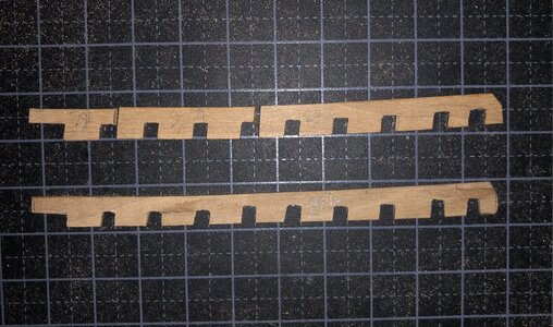
The ex upper of the two waterways in the picture below is the original one I cut into three pieces.
The lower waterway is the one I fabricated today. It fits quite nicely in the hull.
So pleased...

4731331A-D473-4C9B-AFE1-85F3F55220A9.jpeg

In the lower part of the picture below one may see the newly fabricated waterway, also know as part 29.

D0669248-0993-45D4-A99C-FB7BCF22B2CB.jpeg

In order not to get too bored, I switched from the waterways to the keelsons, which where dry fitted in the hull, but still needed to be finished and permanently attached to the ship.
The build instructions call for nails to be used to either simulate the actual bolts/trennels or to attach the keelson to the frames. Since the keelsons fit really snug, I decided to use the "toothpick" method again, instead of using the copper nails, supplied with the kit and bond the keelsons to the frames.

The first, mid hull keelson is in, the fwd- and aft keelsons are still loose, waiting for their toothpick treatment.

Zooming in on the right hand side of the picture below allows you to not only see the trennel simulation in the keelson, but also in the frames. To date I have used 800 toothpicks, two-sided, thus some 1500 odd trennels installed and give or take a 50 toothpicks (100 trennels) wasted.
Before I could start on the trennels in the keelson, I quickly had to walk over to the local supermarket to get me another 800 toothpicks; the amount of effort you have to put into your model, it's staggering... ROTF

4BA84F82-8189-4004-AA6F-D0A12E6785AF.jpeg
 
Last edited:
Today saw me trying to make the two aft waterways, left and right.
As I said, I had some material for this exercise, so after transferring the lines to the pieces of wood, I first filed the outer contours and then used the Dremel, yeah that's right, the Dremel, to make the raw notches. I also tried a handsaw, but that was a pretty bad idea; the wood just broke under the slightest of pressures.
Unfortunately, the right hand waterway broke in three separate pieces, possibly due to a crack already in the wood. Since I don't have sufficient (matching) wood available, I'll resort to @Dean62's suggestion to just open up the notches, see how that works.

The ex upper of the two waterways in the picture below is the original one I cut into three pieces.
The lower waterway is the one I fabricated today. It fits quite nicely in the hull.
So pleased...

View attachment 297055

In the lower part of the picture below one may see the newly fabricated waterway, also know as part 29.

View attachment 297056

In order not to get too bored, I switched from the waterways to the keelsons, which where dry fitted in the hull, but still needed to be finished and permanently attached to the ship.
The build instructions call for nails to be used to either simulate the actual bolts/trennels or to attach the keelson to the frames. Since the keelsons fit really snug, I decided to use the "toothpick" method again, instead of using the copper nails, supplied with the kit and bond the keelsons to the frames.

The first, mid hull keelson is in, the fwd- and aft keelsons are still loose, waiting for their toothpick treatment.

Zooming in on the right hand side of the picture below allows you to not only see the trennel simulation in the keelson, but also in the frames. To date I have used 800 toothpicks, two-sided, thus some 1500 odd trennels installed and give or take a 50 toothpicks (100 trennels) wasted.
Before I could start on the trennels in the keelson, I quickly had to walk over to the local supermarket to get me another 800 toothpicks; the amount of effort you have to put into your model, it's staggering... ROTF

View attachment 297057
It’s looking good, Johan. Nice job with the new waterway.
Regards, Peter
 
Back
Top