YUANQING BLUENOSE - Heinrich

Hello Gentlemen

I have been relatively quiet the last few days as I have been very busy wrapping up the year, writing reports and feedbacks, doing evaluations and the like. @proudtower Paul asked a very good question as to why the holes needed to be drilled. Directly translated, the instructions indicate that this is the "water well", but seeing that that does not tell us much, I started researching and reading ahead ... very far ahead. Now I know exactly what needs to happen but as to what their actual function is on a real ship (unless it forms part of some kind of bilge pump construction), I am not sure. This we will leave to all our historical buffs in the family!:)

PW1.png

You will find these series of photographs on Page 32 of the instruction manual. The two holes are to facilitate fitment of these two hollowed wooden "dowels". The protrusion at the bottom is meant to fit into the respective 2mm x 2mm holes we have drilled.
PWUntitled.png

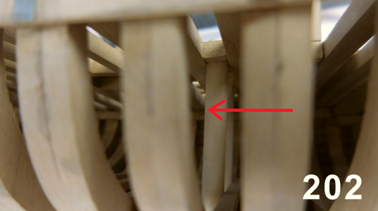
This picture shows the "pressure well" (Xiuli's translation) in their installed positions. (You can see just how far down the line this part actually gets assembled.)

PW 3.png

Now it gets interesting! Remember on Bluenose only the left-hand side of the ship and left-hand side of the deck gets planked. The right-hand side is left exposed to showcase the construction. Clearly marked in translucent Yellow, you can see the unfinished pressure well on the starboard side, while on the port side, the pressure well is finished off to be flush with the deck (blue square). This picture is taken with the bow on the right and the stern on the left.

PW4.png

The final picture shows on the completed "pressure well / water well" assembly on the Port Side (Red Square) while the Starboard Side is left unfinished (Yellow Square).

That gentlemen, is why we drilled the two holes! :)
 
Hello Gentlemen

I have been relatively quiet the last few days as I have been very busy wrapping up the year, writing reports and feedbacks, doing evaluations and the like. @proudtower Paul asked a very good question as to why the holes needed to be drilled. Directly translated, the instructions indicate that this is the "water well", but seeing that that does not tell us much, I started researching and reading ahead ... very far ahead. Now I know exactly what needs to happen but as to what their actual function is on a real ship (unless it forms part of some kind of bilge pump construction), I am not sure. This we will leave to all our historical buffs in the family!:)

View attachment 203680

You will find these series of photographs on Page 32 of the instruction manual. The two holes are to facilitate fitment of these two hollowed wooden "dowels". The protrusion at the bottom is meant to fit into the respective 2mm x 2mm holes we have drilled.

View attachment 203681

This picture shows the "pressure well" (Xiuli's translation) in their installed positions. (You can see just how far down the line this part actually gets assembled.)

View attachment 203682

Now it gets interesting! Remember on Bluenose only the left-hand side of the ship and left-hand side of the deck gets planked. The right-hand side is left exposed to showcase the construction. Clearly marked in translucent Yellow, you can see the unfinished pressure well on the starboard side, while on the port side, the pressure well is finished off to be flush with the deck (blue square). This picture is taken with the bow on the right and the stern on the left.

View attachment 203685

The final picture shows on the completed "pressure well / water well" assembly on the Port Side (Red Square) while the Starboard Side is left unfinished (Yellow Square).

That gentlemen, is why we drilled the two holes! :)
Regarding a "water well" or correctly the two water wells they were and are located on both sides of the keel in a cement ballast well to collect the bilge water for pumping up and out onto the deck. Typically located just aft of the main mast as presented in the kit. Borrowing with credits to Bluenose II Saga of the Fishing Schooners I will use the illustration and explanatory textPump and Well Assembly.jpg
Now focusing on the lower left textWater Wells and Pumps.jpg
In addition to concrete ballast were various items and when racing the anchors were placed below as additional ballast. Rich
 
Don I will do that tomorrow morning first thing. Today I worked only on my big ship - I'm trying to keep that going forward as well. But I promise, tomorrow, I will do Frame #3.
 
Hello Everyone.

Build-wise it has been quiet for me on the Bluenose front, because I'm rushing to meet a self-imposed deadline with the Haarlem and work at the moment is just a challenge, top put it mildly. With Chinese New Year around the corner (a month away from the biggest festival and celebration in the world), work is just hectic.

However I need to draw your urgent attention to the following:

ANNOUNCEMENT Exclamation-Mark CORRECTION Exclamation-Mark

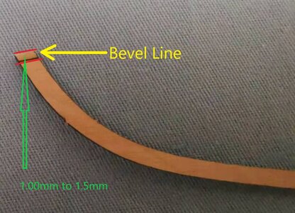
In my log you will recall how I showed you the beveling needs to be done for Part #20. Just to refresh ...

Build 41.jpg

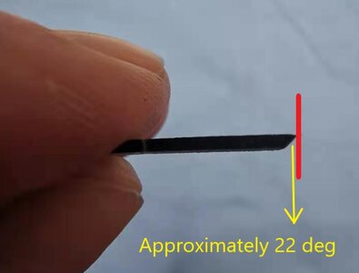
I then beveled the line - in the only way that I knew and could think of - to the outside.

Build 42.jpg

Build 44.jpg

Build 45.jpg

HOWEVER: This morning, @Peter Voogt Peter sent me a very clear explanation why this is not right.

First off Peter told me that Part #20 extends past the Centre Keel (Part #8) on his build. On mine it didn't - but if you look at Drawing 47, Peter is 100% right.

4C0E6788-B68C-4C2B-A21C-8CD9784C48E5.jpg

Note how Part #20 extends past the top of the Centre Keel. Also note that no beveling has taken place yet.

8D9E6C3B-95A6-490C-B336-B73820D14636.jpg

Exclamation-Mark Exclamation-Mark Exclamation-Mark AND HERE IS WHY. PART #20 NEEDS TO BE BEVELED TO THE INSIDE SO THAT IT FORMS A VALLEY ... Exclamation-MarkExclamation-MarkExclamation-Mark

0DF1C4E7-99F5-46C7-96ED-27B2CA792079.jpeg

Exclamation-MarkExclamation-MarkExclamation-MarkFOR THE BOWSPRIT TO FIT INTO !!! Exclamation-MarkExclamation-MarkExclamation-Mark

For those who have already beveled #Part 20, Peter was so kind as to share his suggestion as to remedy the situation.

DAEDA657-6B26-4A1F-B9ED-F45C76BD286C.jpeg

It is not a train smash as you still maintain the valley for the bowsprit to rest in.

Gentlemen - please accept my apologies - this was my mistake out and out! Please beware of this and once more a VERY BIG THANK YOU TO @Peter Voogt PETER FOR POINTING THIS OUT.

Kind regards - A very red-faced HeinrichSickSickSick
 
No need for a red face Heinrich, this is called "!@# happens". Not to worry bud. Mine are the same sitting above the keel(#8), I did not bevel mine yet as I thought I screwed something up and was waiting until the final moment to deal with it.
At the risk of being rude.... the above fix, has the centre piece been filed down? If so I don't think this will work as the diameter of the bowsprit is 4 mm and the space left between the two # 20 pieces is just over 2 mm. If the middle part has been filed down will that not affect the angle of the bowsprit?
Again I do not want to sound rude about this, just curious.
Nice catch Peter!! :)
 
Last edited by a moderator:
Hello everybody,
The picture @Heinrich showed with “my suggestion” was the picture about why I made myself the Why-question.
And thats why it gives the ?? by @DonRobinson!
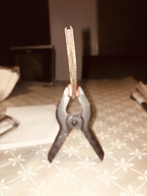
This is my solution: Make 2 little bevels on the inside and you get the gaffel/valley:
Keel.jpg
Sorry for not sharp, but the iPhone does not do what I wanted it to do ;).

PS:
If you wanted to use the bevel-lines on the parts #20:
-use part #20 out the starboard-sheet, make the bevel, and place it on the port side of the keel. With the bevel inside!
-vice versa with the part #20 out the port-sheet.
Regards, Peter
 
Last edited:
I agree, that this modification / problem probably needs to be mentioned on the first page of Heinrich Build or the first page of the support section so people will see this when they first start their project.
EDIT: I have now added a link to the support page that will link to what Heinrich is saying on his post.

thanks
Donald
 
Back
Top