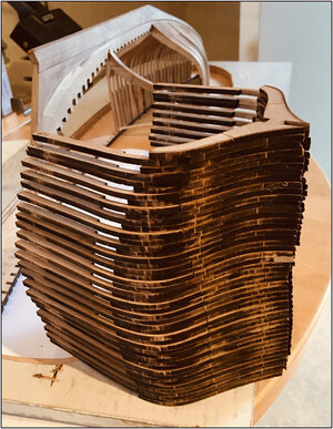
Dean, with your young age you have the stamina and endurance to work those long hours. Don't waste any of them as they are then gone. RichResults speak for themselves! You do very good work Peter. I joke with you about time, but I wish I could do the same! I’m still working 50 hrs a week, so I have to work in the evenings when I can. Or put in a full day on the weekend!
-

Win a Free Custom Engraved Brass Coin!!!
As a way to introduce our brass coins to the community, we will raffle off a free coin during the month of August. Follow link ABOVE for instructions for entering.
-

PRE-ORDER SHIPS IN SCALE TODAY!
The beloved Ships in Scale Magazine is back and charting a new course for 2026!
Discover new skills, new techniques, and new inspirations in every issue.
NOTE THAT OUR FIRST ISSUE WILL BE JAN/FEB 2026
- Home
- Forums
- Ships of Scale Group Builds and Projects
- Bluenose PoF Group Build
- Bluenose Group Build Logs
You are using an out of date browser. It may not display this or other websites correctly.
You should upgrade or use an alternative browser.
You should upgrade or use an alternative browser.
YUANQING BLUENOSE - Peter Voogt [COMPLETED BUILD]
- Thread starter Peter Voogt
- Start date
- Watchers 74
With your hours in mind, hats off to your progress.Results speak for themselves! You do very good work Peter. I joke with you about time, but I wish I could do the same! I’m still working 50 hrs a week, so I have to work in the evenings when I can. Or put in a full day on the weekend!

I am in the luxury position that I could stop, after 45 years of working. And now I'm just busier .
Regards, Peter
Busy assembling the frames 23 to 48, I had to have some distractions.
At the beginning of this build-log, I had already said that I would like to turn this report into a photo book later. To show interested parties how the construction went, without having internet at hand.
I had already posted a few photos of the first small frames, but they consisted of only 2 parts: the front and back combination of the floor, futtocks and top timber.
I had already made a photo compilation of the steps for making the bevels.
On the Dutch forum, there is not published about the build of the BN so many as on this forum. Therefore I made for the Dutch forum a picture compilation of the steps I made for each frame.
And show it also here, because …….. I build the frame a little bit different ……..
It is recommended to build the front and rear frames separately on the frame drawings. I deviated from that because then in 1st instance you glue only small areas together. I have built up the frames step by step from the floor parts, with part by part the futtocks and top timbers.
The first 9 steps:
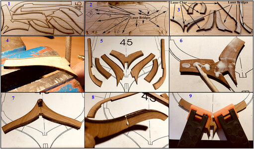
1: Depending on the size of the frames to be made, composed of a front and a rear frame, the parts are in 1 or 2 shelves. The parts are lasered. The largest frames consist of 7 parts. In my post #103 I have already explained the making of the bevels with the laser lines.
2: The parts are marked at the back with a 'X', because these sides are glued together. If you glue the wrong side, you change the laser lines. The laser cut-out is not complete. The parts are still stuck in the shelf with bridges.
3: Sometimes you have to cut the bridges, but usually the particles are easy to express. All edges are charred from lasering. In the end, all that has to be done, along with the bridges.
4: First remove the bridges and char on the sides that are glued together. Otherwise, the glue won't held. I do that on top of my table vice and with a sweet file. So I'll work straight and right.
Because it may be known: the laser cuts at a small angle! And usually you have not succeeded in the two surfaces to be glued with corresponding sloping surfaces falling exactly against each other. So flatten everything at right angles.
5: All 7 parts processed and ready to assemble. All in all, 30 small or bigger sides filed.
6: First the front and back 'floor' pieces together. With a toothpick I make sure that a film of glue is put all over the surface. This is the 'floor' of the 'back frame'.
7: The ‘floor’ of the front frame consists of 2 parts. With a fitting block with the width of the keel in the appropriate recess, it’s placed, lightly pressed and ensured that the (later) upwards sides connect to each other.
8: Based on the excess glue that comes out between the parts, I can immediately see to connect the parts nicely together. Otherwise just loosen, clean, file and glue again.
9: If the fit is correct, then the parts on the drawing to check and clamp your correct shape.
The second 9 steps:
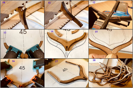
10: Because I can now easily maneuver under the keel, I use the ‘floor’ to file the corresponding recess in the keel to width.
11: Now I make the recess between the noses of the ‘floor’ at the right width so that later when placing the frame, with a little resistance, it will slide over the keel. On the SoS forum there are already several examples of broken struts. They are thin. And if they also do not slide nicely into the recesses in the jig, then it clamps and wrings above and below. Then file and sand gives much more stress. In your head and in your frames.
12: And because I am fitting now, also the corresponding recess in the keelson. And I'll make straights in the keelson. Because there too, the laser cuts are on a angle!.
It works much easier than later with the placement. Where it has to fit over all the Frames. Then find out which doesn't fit ……..
13: Now it is the turn of the two parts '1st futtock' of the rear frame, the 'belly pieces'. Gluing, fitting and clamping. They are here in the drawing with the 2 floor pieces on top of it. The clamps press the new joint through these pieces.
14: Once dry, turned over. With the continuous laser lines for the bevel, in accordance with the drawing.
15: Then the two parts 'top timber' of the front frames, the 'struts'.
Again bulging glue in the fitting. Remove with a wet rag and ....
16: Fit the drawing and clamp to dry. With the glue clamps on the pieces '1st futtock', which therefore press on this new connection.
17: Once dry, a frame ready to make the bevels.
18: Mark the frame with its number and on the others and on to the next one.
IMNO, so I build a solid frame step by step.
Regards, Peter
At the beginning of this build-log, I had already said that I would like to turn this report into a photo book later. To show interested parties how the construction went, without having internet at hand.
I had already posted a few photos of the first small frames, but they consisted of only 2 parts: the front and back combination of the floor, futtocks and top timber.
I had already made a photo compilation of the steps for making the bevels.
On the Dutch forum, there is not published about the build of the BN so many as on this forum. Therefore I made for the Dutch forum a picture compilation of the steps I made for each frame.
And show it also here, because …….. I build the frame a little bit different ……..
It is recommended to build the front and rear frames separately on the frame drawings. I deviated from that because then in 1st instance you glue only small areas together. I have built up the frames step by step from the floor parts, with part by part the futtocks and top timbers.
The first 9 steps:

1: Depending on the size of the frames to be made, composed of a front and a rear frame, the parts are in 1 or 2 shelves. The parts are lasered. The largest frames consist of 7 parts. In my post #103 I have already explained the making of the bevels with the laser lines.
2: The parts are marked at the back with a 'X', because these sides are glued together. If you glue the wrong side, you change the laser lines. The laser cut-out is not complete. The parts are still stuck in the shelf with bridges.
3: Sometimes you have to cut the bridges, but usually the particles are easy to express. All edges are charred from lasering. In the end, all that has to be done, along with the bridges.
4: First remove the bridges and char on the sides that are glued together. Otherwise, the glue won't held. I do that on top of my table vice and with a sweet file. So I'll work straight and right.
Because it may be known: the laser cuts at a small angle! And usually you have not succeeded in the two surfaces to be glued with corresponding sloping surfaces falling exactly against each other. So flatten everything at right angles.
5: All 7 parts processed and ready to assemble. All in all, 30 small or bigger sides filed.
6: First the front and back 'floor' pieces together. With a toothpick I make sure that a film of glue is put all over the surface. This is the 'floor' of the 'back frame'.
7: The ‘floor’ of the front frame consists of 2 parts. With a fitting block with the width of the keel in the appropriate recess, it’s placed, lightly pressed and ensured that the (later) upwards sides connect to each other.
8: Based on the excess glue that comes out between the parts, I can immediately see to connect the parts nicely together. Otherwise just loosen, clean, file and glue again.
9: If the fit is correct, then the parts on the drawing to check and clamp your correct shape.
The second 9 steps:

10: Because I can now easily maneuver under the keel, I use the ‘floor’ to file the corresponding recess in the keel to width.
11: Now I make the recess between the noses of the ‘floor’ at the right width so that later when placing the frame, with a little resistance, it will slide over the keel. On the SoS forum there are already several examples of broken struts. They are thin. And if they also do not slide nicely into the recesses in the jig, then it clamps and wrings above and below. Then file and sand gives much more stress. In your head and in your frames.
12: And because I am fitting now, also the corresponding recess in the keelson. And I'll make straights in the keelson. Because there too, the laser cuts are on a angle!.
It works much easier than later with the placement. Where it has to fit over all the Frames. Then find out which doesn't fit ……..
13: Now it is the turn of the two parts '1st futtock' of the rear frame, the 'belly pieces'. Gluing, fitting and clamping. They are here in the drawing with the 2 floor pieces on top of it. The clamps press the new joint through these pieces.
14: Once dry, turned over. With the continuous laser lines for the bevel, in accordance with the drawing.
15: Then the two parts 'top timber' of the front frames, the 'struts'.
Again bulging glue in the fitting. Remove with a wet rag and ....
16: Fit the drawing and clamp to dry. With the glue clamps on the pieces '1st futtock', which therefore press on this new connection.
17: Once dry, a frame ready to make the bevels.
18: Mark the frame with its number and on the others and on to the next one.
IMNO, so I build a solid frame step by step.
Regards, Peter
Last edited:
Very methodical approach Peter. I expect nothing less from you!Busy assembling the frames 23 to 48, I had to have some distractions.
At the beginning of this build-log, I had already said that I would like to turn this report into a photo book later. To show interested parties how the construction went, without having internet at hand.
I had already posted a few photos of the first small frames, but they consisted of only 2 parts: the front and back combination of the floor, futtocks and top timber.
I had already made a photo compilation of the steps for making the bevels.
On the Dutch forum, there is not published about the build of the BN so many as on this forum. Therefore I made for the Dutch forum a picture compilation of the steps I made for each frame.
And show it also here, because …….. I build the frame a little bit different ……..
It is recommended to build the front and rear frames separately on the frame drawings. I deviated from that because then in 1st instance you glue only small areas together. I have built up the frames step by step from the floor parts, with part by part the futtocks and top timbers.
The first 9 steps:
View attachment 227534
1: Depending on the size of the frames to be made, composed of a front and a rear frame, the parts are in 1 or 2 shelves. The parts are lasered. The largest frames consist of 7 parts. In my post #103 I have already explained the making of the bevels with the laser lines.
2: The parts are marked at the back with a 'X', because these sides are glued together. If you glue the wrong side, you change the laser lines. The laser cut-out is not complete. The parts are still stuck in the shelf with bridges.
3: Sometimes you have to cut the bridges, but usually the particles are easy to express. All edges are charred from lasering. In the end, all that has to be done, along with the bridges.
4: First remove the bridges and char on the sides that are glued together. Otherwise, the glue won't held. I do that on top of my table vice and with a sweet file. So I'll work straight and right.
Because it may be known: the laser cuts at a small angle! And usually you have not succeeded in the two surfaces to be glued with corresponding sloping surfaces falling exactly against each other. So flatten everything at right angles.
5: All 7 parts processed and ready to assemble. All in all, 30 small or bigger sides filed.
6: First the front and back 'floor' pieces together. With a toothpick I make sure that a film of glue is put all over the surface. This is the 'floor' of the 'back frame'.
7: The ‘floor’ of the front frame consists of 2 parts. With a fitting block with the width of the keel in the appropriate recess, it’s placed, lightly pressed and ensured that the (later) upwards sides connect to each other.
8: Based on the excess glue that comes out between the parts, I can immediately see to connect the parts nicely together. Otherwise just loosen, clean, file and glue again.
9: If the fit is correct, then the parts on the drawing to check and clamp your correct shape.
The second 9 steps:
View attachment 227536
10: Because I can now easily maneuver under the keel, I use the ‘floor’ to file the corresponding recess in the keel to width.
11: Now I make the recess between the noses of the ‘floor’ at the right width so that later when placing the frame, with a little resistance, it will slide over the keel. On the SoS forum there are already several examples of broken struts. They are thin. And if they also do not slide nicely into the recesses in the jig, then it clamps and wrings above and below. Then file and sand gives much more stress. In your head and in your frames.
12: And because I am fitting now, also the corresponding recess in the keelson. And I'll make straights in the keelson. Because there too, the laser cuts are on a angle!.
It works much easier than later with the placement. Where it has to fit over all the Frames. Then find out which doesn't fit ……..
13: Now it is the turn of the two parts '1st futtock' of the rear frame, the 'belly pieces'. Gluing, fitting and clamping. They are here in the drawing with the 2 floor pieces on top of it. The clamps press the new joint through these pieces.
14: Once dry, turned over. With the continuous laser lines for the bevel, in accordance with the drawing.
15: Then the two parts 'top timber' of the front frames, the 'struts'.
Again bulging glue in the fitting. Remove with a wet rag and ....
16: Fit the drawing and clamp to dry. With the glue clamps on the pieces '1st futtock', which therefore press on this new connection.
17: Once dry, a frame ready to make the bevels.
18: Mark the frame with its number and on the others and on to the next one.
IMNO, so I build a solid frame step by step.
Regards, Peter
Great job as always!
Very methodical approach Peter. I expect nothing less from you!
Great job as always!
Thanxs Dean and Heinrich.Indeed this method makes a lot of sense, Peter!
Sometime a little bit c..... and a little change ......
Regards, Peter
- Joined
- Oct 28, 2018
- Messages
- 760
- Points
- 403

Nice comprehensive manual Peter,
Very valuable, and I will certainly use it when I start on my BN.
Thanks for sharing
Very valuable, and I will certainly use it when I start on my BN.
Thanks for sharing
Thanxs Henk.Nice comprehensive manual Peter,
Very valuable, and I will certainly use it when I start on my BN.
Thanks for sharing
Finish the sub .........
Regards, Peter
I love a good pun. Well placed. RichAnd when you use frame 45 as example, 48 is not far away:
View attachment 227539
The bump was a mess, so just piled up.
Now make time to bevel all the frames and get rid of the char.
This kit and the frames has a lot of 'char'acter.
Regards, Peter
- Joined
- Jan 9, 2020
- Messages
- 10,566
- Points
- 938

You are right Peter. I can only think that the char has to do something with the heat at which the laser cutter operates. I think we can all agree that the accuracy of the laser cutting is superb, so maybe the extra heat assures the accuracy and clean cutting at the cost of having more char. What you gain on the swings ...
You are correct Heinrich. Laser = heat = char. You can prevent it from char by cooling with water.You are right Peter. I can only think that the char has to do something with the heat at which the laser cutter operates. I think we can all agree that the accuracy of the laser cutting is superb, so maybe the extra heat assures the accuracy and clean cutting at the cost of having more char. What you gain on the swings ...
But thats not the best for the accuracy
 .
.The ‘heat’ and ‘char’ remind me now to the fine motion picture: “Char(’)iots of Fire”. With beautifull music of Vangelis.
Regards, Peter
Hi Rich,Your are correct about the cement and pig iron internal ballast in BN. It was formed out at the pumps creating a well in those locations. BN did not carry an external ballast that was a metal shoe or band on the very bottom of the keel. Just think, . . you too could simulate the internal ballast and pump wells LOL. . . nice work. Rich
What you suggested, the pump wells, I had already in my head, but I didn't want to tell you that moment ......
When working the frames I arrived at 31. Time for a little intermezzo.
In frame 31, 2 holes of 2 mm must be drilled. In it, the water pumps come to rest with their feet. But how do they get their water supplied?
I got some inspiration in The Saga, from which Rich has posted this, concerning the BN-II:
The feet of the two pumps are in 2 wells. These are between 2 frames and inlaid in the cement ballast floor.Regarding a "water well" or correctly the two water wells they were and are located on both sides of the keel in a cement ballast well to collect the bilge water for pumping up and out onto the deck. Typically located just aft of the main mast as presented in the kit. Borrowing with credits to Bluenose II Saga of the Fishing Schooners I will use the illustration and explanatory textView attachment 203692
Now focusing on the lower left textView attachment 203693
In addition to concrete ballast were various items and when racing the anchors were placed below as additional ballast. Rich
With the kit, the two pumps are aligned in the frames, beams and decks, and fitted IN frame 31. Now I can turn all this around, but I have opted for an interim solution. Some artistic license
And the original BN probably did not have the cement ballast floor, but had 'loose' ballast, consisting of stones and waste pieces of cast iron.
Drilled on both sides a hole and attached copper tubes of 2.5 mm. Now the water can flow from front and back to the foot of the pump.
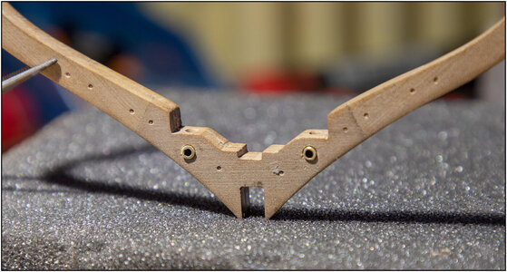
To catch the water around the supply, 4 wells come between the frames. The first assembled, made of copper foil:
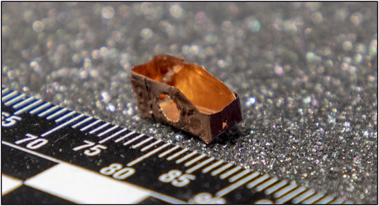
WxDxH 9.5 x 4 x 4.5 mm, with a 2.5 mm opening for transit.
The pure copper on the inside, a protection layer on the outside.
Between the frames 30 and 31:
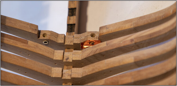
And seen from the outside:
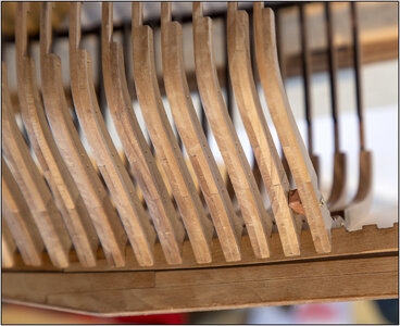
3 others still te go.
Do you going to see any of them later? At least on the side that won't get the hull planks. And on the other side? Maybe from the inside ........
And don't forget....... You know they're there .....
Regards, Peter
Last edited:
Wow, that is absolutely ingenious. What a nice add to your BN.
Jan
Jan
Thanxs Jan,Wow, that is absolutely ingenious. What a nice add to your BN.
Jan
And I have still so many ideas ..... but I show when I am that far.
Regards, Peter
Peter, your creativity is non-stoppable! This is what makes our hobby most fun! Among all BN purchased there will be no one alike. But some models will be spot on, and I do know one of those for sure! 
Phoe Phoe, Jim ...... thanxs ....... It makes me a little quiet and makes me blush.Peter, your creativity is non-stoppable! This is what makes our hobby most fun! Among all BN purchased there will be no one alike. But some models will be spot on, and I do know one of those for sure!
Regards, Peter
Last edited:
Great stuff Peter, I know your attention to detail!Hi Rich,
What you suggested, the pump wells, I had already in my head, but I didn't want to tell you that moment ......
When working the frames I arrived at 31. Time for a little intermezzo.
In frame 31, 2 holes of 2 mm must be drilled. In it, the water pumps come to rest with their feet. But how do they get their water supplied?
I got some inspiration in The Saga, from which Rich has posted this, concerning the BN-II:
The feet of the two pumps are in 2 wells. These are between 2 frames and inlaid in the cement ballast floor.
With the kit, the two pumps are aligned in the frames, beams and decks, and fitted IN frame 31. Now I can turn all this around, but I have opted for an interim solution. Some artistic license
And the original BN probably did not have the cement ballast floor, but had 'loose' ballast, consisting of stones and waste pieces of cast iron.
Drilled on both sides a hole and attached copper tubes of 2.5 mm. Now the water can flow from front and back to the foot of the pump.
View attachment 230321
To catch the water around the supply, 4 wells come between the frames. The first assembled, made of copper foil:
View attachment 230316
WxDxH 9.5 x 4 x 4.5 mm, with a 2.5 mm opening for transit.
The pure copper on the inside, a protection layer on the outside.
Between the frames 30 and 31:
View attachment 230318
And seen from the outside:
View attachment 230319
3 others still te go.
Do you going to see any of them later? At least on the side that won't get the hull planks. And on the other side? Maybe from the inside ........
And don't forget....... You know they're there .....
Regards, Peter
Thanxs Dean, it’s our personal touch, to make from the same kit a individual (Unique) BN.Great stuff Peter, I know your attention to detail!
Regards, Peter
My understanding of the pump wells is that the pump shafts did not drop onto/into a frame but were between frames where the concrete ballast had been formed out, like an area drain well in a parking lot for the bilge water to drain into the open topped area. The pump shafts were located in the middle of these wells with the bottom end below the top of the well to gather and pump up the bilge water. I think that the kit put them into the frame and not between for their own reasons. The copper well idea creates the collection well for the "piped bilge water to drain laterally to the bottom of the pump shaft. Good idea for the needs of the YQ kit. Just my own understanding of the bilge pumps and wells. RichThanxs Dean, it’s our personal touch, to make from the same kit a individual (Unique) BN.
Regards, Peter


