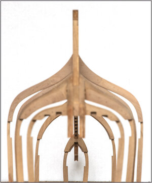
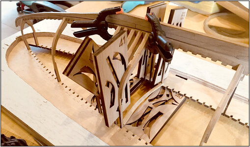
YUANQING BLUENOSE - Peter Voogt [COMPLETED BUILD]

Hello Peter - I am catching up somewhat today with all the wonderful work that has been done. Your frames look meticulously clean and the wells are a most welcome and personal addition to the build. For me it is wonderful to see the many interpretations of BN and how each exemplifies the character and personality of the builder. There is actually much one can gather from the builder by just looking at the different logs.
 
Looking great Peter! You are almost ready to glue into the jig and start internal framework! ;)
I can’t wait ….. but the stern is also a challenge.
A present for you my friend, as I can see you adding this! ;) The motor that was used on the windlass!
It's too late for me to add this detail, but it would have been fun to scratch build. :)
View attachment 231530
Uuuh …. How can you read my mind :rolleyes:?
Also a challenge.
The engine and gear box have hinges for a reason :) ....
Regards, Peter
 
Last edited:
Ca Chug. . . Ca Chug. . . Ca Chug, Chud, Chug . . . Po;p!!! Roar!!!!!!! Sputter. . . " "*** forgot to fill her up!" Redface Rich
Peter will know how to take care of this. Rich
Hi Rich,
Don’t increase the pressure ….. for the engine and my challenge :)
Regards, Peter
 
Last edited:
Hello Peter - I am catching up somewhat today with all the wonderful work that has been done. Your frames look meticulously clean and the wells are a most welcome and personal addition to the build. For me it is wonderful to see the many interpretations of BN and how each exemplifies the character and personality of the builder. There is actually much one can gather from the builder by just looking at the different logs.
Hi Heinrich.
Thank you very much for your kind words. Now the amount of build-log and there length is growing, you can see and compare more and more. Different speed of building and posting etc. Or even not started a build-log. ;)
In any case, it should not be an obstacle for the other BN owners to show their build in particular. Although the most stages have been show, every personal interpretation is interesting to follow.
And overall: it is no competition, on any part of the builder build-log!
But on the other hand: can you follow 37 BN build-logs?:) (See the BN-list til now)
Regards, Peter
 
Last edited:
Uuuh …. How can you read my mind :rolleyes:?
Also a challenge.
Regards, Peter
In the Netherlands we have a big collectors fair:
When they opens again after the Covid-19, I had in mind to visit them for surching parts for the windlass. Parts for the motor are added to the list :).
The possible data are:
De NAMAC-beursdata voor 2021 zijn:
19 juni
21 augustus
16 oktober
4 december

And perhaps this is a option:

Regards, Peter
 
Last edited:
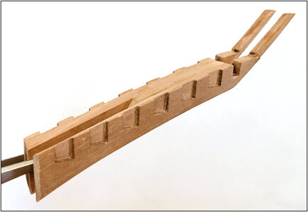
First I started assembling the keel part of the stern.
Dean @Dean62 has introduced ‘Artistic License’ (AL). I will add ‘Free Interpretation’ (FI). Together it is AL-FI. :D

So, AL-FI says:
The manual describes to glue these 2 longitudinal parts to the keel.
I chose to put them together separately. Together with part #53, which actually is on page 14 in step/photo 82/83. But I think that part gives more solidity:
093 Kiel53.jpg

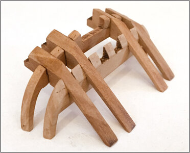
Because I was busy with all parts of the stern, also these parts were prepared dry-fit:
094 KielStern.jpg
After fitting on the keel, it will be adjusted on bevel and angle.

I then fitted the keel part, together with the half frames 50 and 55, to the keel. With the smooth connection to the frame 49:
095 Kiel.jpg

Taken away frame 50 and the keel part glued and clamped:
096 Kiel.jpg

The whole construction of the stern is depending of this joint. So I believe the connection of these main parts is not only glued. I have, with AL-FI, chosen to strengthen the connection of the stern part to the keel.
I used the technic I encountered in the build-log of Maarten @Maarten :
But also Jim @Jimsky gives a nice explatantion in his Alert build-log about the cup burr and the treenails with a syringe.
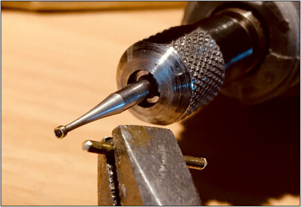
The cup burr must be bigger then the wire, or the wire has to be pointed. Otherwise the cup burr won’t center:
097 Burr.jpg

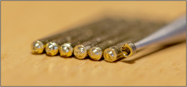
With brass 1,2 mm and a cup burr of 1,2 mm, a made 6 rods/nails:
098 Burr.jpg
There is some brass in the burr, forgotten to clean it for the picture. ;)
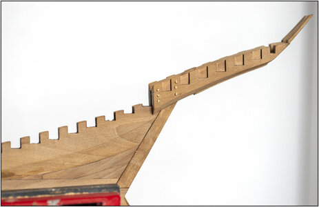
The construction:
099 Burr.jpg

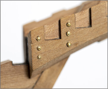
In detail:
100 Burr.jpg
The angle of both parts is the same as on the drawing of the manual. Practice and theory come’s (again) together.

Perhaps you won’t see it any more when the build is completed, but ..... you know it’s there.;)

So, now I am ready the glue the frames in the jig and on the keel.
Regards, Peter
 
Last edited:
First I started assembling the keel part of the stern.
Dean @Dean62 has introduced ‘Artistic License’ (AL). I will add ‘Free Interpretation’ (FI). Together it is AL-FI. :D

So, AL-FI says:
The manual describes to glue these 2 longitudinal parts to the keel.
I chose to put them together separately. Together with part #53, which actually is on page 14 in step/photo 82/83. But I think that part gives more solidity:
View attachment 232438

Because I was busy with all parts of the stern, also these parts were prepared dry-fit:
View attachment 232439
After fitting on the keel, it will be adjusted on bevel and angle.

I then fitted the keel part, together with the half frames 50 and 55, to the keel. With the smooth connection to the frame 49:
View attachment 232440

Taken away frame 50 and the keel part glued and clamped:
View attachment 232441

The whole construction of the stern is depending of this joint. So I believe the connection of these main parts is not only glued. I have, with AL-FI, chosen to strengthen the connection of the stern part to the keel.
I used the technic I encountered in the build-log of Maarten @Maarten :
The cup burr must be bigger then the wire, or the wire has to be pointed. Otherwise the cup burr won’t center:
View attachment 232442

With brass 1,2 mm and a cup burr of 1,2 mm, a made 6 rods/nails:
View attachment 232443
There is some brass in the burr, forgotten to clean it for the picture. ;)
The construction:
View attachment 232444

In detail:
View attachment 232445
The angle of both parts is the same as on the drawing of the manual. Practice and theory come’s (again) together.

Perhaps you won’t see it any more when the build is completed, but ..... you know it’s there.;)

So, now I am ready the glue the frames in the jig and on the keel.
Regards, Peter
Interesting technique to simulate washers.
As far as support goes, that glue joint will be sufficient, as the stern frames will get additional support from the internal beams that run laterally, the deck beams, the deck, the waterway boards, external planking, railings, etc. It is all tied together very well in the end! ;)
 
Kudos to you and AL-FI. That looks fantastic.
Jan
Thanxs Jan, AL-FI will be a great help by the rest of the build ;).
Interesting technique to simulate washers.
As far as support goes, that glue joint will be sufficient, as the stern frames will get additional support from the internal beams that run laterally, the deck beams, the deck, the waterway boards, external planking, railings, etc. It is all tied together very well in the end! ;)
Hi Dean, you will soon see some more. :) I have 0,8, 1,0 and 1,2 mm cup burr’s.
By the keelson and internal beams, YQ simulate them with the nails.
Therefore, the simulation also by this joint.
Didn t keep up with your blog for a while but you are making quite some progress.
Nice build and now al the frames are finished the fun really starts.
Thank you, Maarten. Yes, keel, frames, keelson and stern can now fit together, to give her the beautifull shape. A lot of preparations with all those bevels and char, but now we are off.

Regards, Peter
 
Thanxs Jan, AL-FI will be a great help by the rest of the build ;).

Hi Dean, you will soon see some more. :) I have 0,8, 1,0 and 1,2 mm cup burr’s.
By the keelson and internal beams, YQ simulate them with the nails.
Therefore, the simulation also by this joint.

Thank you, Maarten. Yes, keel, frames, keelson and stern can now fit together, to give her the beautifull shape. A lot of preparations with all those bevels and char, but now we are off.

Regards, Peter
Regarding your helming of AL-FI and your successful result it reminded me of the Naval Aviation pilots' adage "Any landing is a good landing!!!" and you brought her safely to the dock. Rich ((PT-2)
 
Hi Dean, you will soon see some more. :) I have 0,8, 1,0 and 1,2 mm cup burr’s.
By the keelson and internal beams, YQ simulate them with the nails.
Therefore, the simulation also by this joint.
Regards, Peter
I’m sure you will make it look nice Peter! I always look forward to your version of the Bluenose, because I know that you, like me, take your own approach to detail. Keep up the good work! :)
 
Regarding your helming of AL-FI and your successful result it reminded me of the Naval Aviation pilots' adage "Any landing is a good landing!!!" and you brought her safely to the dock. Rich ((PT-2)
Rich, It's great that memories come up, especially after a piece of FI from my side.
(Haha, in my old job, FI it stands for ‘Forensic Intelligence’. So, back to the roots.)
I’m sure you will make it look nice Peter! I always look forward to your version of the Bluenose, because I know that you, like me, take your own approach to detail. Keep up the good work! :)
Thanxs Dean, for your nice words.
I like! There is no such thing as "over-engineering", so the stronger the better!
Hi Heinrich, thanxs for this conformation.
I think, by the original BN, they didn't just leave that connection by only glueing. Without reinforcement, it would be ‘bad-enginering’. ;)
Regards, Peter
 
Before placing the frames I took the time to align the keel and 1st frames well: straight and at right angles, in a longitudinal and transverse direction.
Other than the manual, I've followed the advice in this interesting post from Dave @Dave Stevens (Lumberyard) in the Druid build-log from Donnie @Donnie :
Special this lines:
“Never ever start at one end and work you way to the other end.
I will always set the midship frame up and the last whole frame forward and aft. Then set up a frame between midship and those last whole frames. Then I will fill in the rest of the frames.”

This became the setup:
101 Uitlijnen.jpg
-1st, the frames 1 and 49;
-2nd , I added the 2 half frames 50 and 55, because they are glued on the side of the keel and ensure ideal vertical alignment;
-3th , frame 25 halfway;
-4th , frame 13 and 37 in between.
According to the hook by frame 25, everything is straight. :)

BUT: See the insert picture above-left. Before I started placing the frames, I first made the bevel in the top of the rabbet on both sides of the keel. Which is much discussed here in the Bluenose Group Build Logs. With the keel separate from everything, it could be nice and flat on my work table with a small chisel.
Now the noses of the frames fits nicely to the bevel and the hull planks (garboards) can slide from the frames into the rabbet. Once all frames have been placed, I can adjust the bevel definitively.
Note: It is just my AL-FI, nobody has to follow this up.Speechless

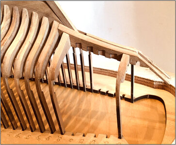
And for the vertically alignment this photo:
102 Uitlijnen.jpg
Taken with the stern to the camera. You never get everything in focus over that length. (Or you have to stich several pictures from 1 fixed point of view with different stages of focus) Therefore, the sharpness is chosen on frame 1. The silhouette of the double back piece still shows itself nicely on either side. To check that everything is straight and parallel to each other.
PS: Sorry Jim @Jimsky still not a cathedral.

All in all, this already gives a lot of strength. A good basis for the rest of the frames.
Regards, Peter
 
Last edited:
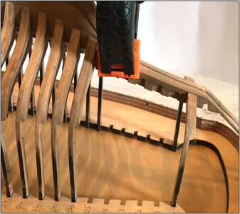
After some questions on the Dutch forum, a picture how I glue the frames.
Working from frame 25, alternately a frame to the bow and to the stern.
Perhaps a overkill, but .....
103 Uitlijnen.jpg
-a frame with a clamp on the keel, to prevent it from being pulled down when further tightening;
- glued the ends of the frames into the jig and tensioned them in the frames with a slat. Under the jig a few frame boards because I have the jig on 2 aluminum profiles for perfectly flat. So the ends will not go lower then the underside of the jig;
-between the frames fit exactly 2 frame boards. Because some frames are slightly curved (or not 90 degree angled overall ;)) and now dry right next to each other.
Regards, Peter
 
Last edited:
Back
Top