YUANQING BLUENOSE - Peter Voogt [COMPLETED BUILD]

My understanding of the pump wells is that the pump shafts did not drop onto/into a frame but were between frames where the concrete ballast had been formed out, like an area drain well in a parking lot for the bilge water to drain into the open topped area. The pump shafts were located in the middle of these wells with the bottom end below the top of the well to gather and pump up the bilge water. I think that the kit put them into the frame and not between for their own reasons. The copper well idea creates the collection well for the "piped bilge water to drain laterally to the bottom of the pump shaft. Good idea for the needs of the YQ kit. Just my own understanding of the bilge pumps and wells. Rich
Hi Rich,
See my text in my post 233 for the same conclusion about the place of the pumps by the BN-II.
Regards, Peter
 
Last edited:
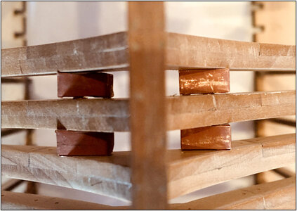
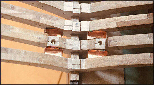
Based on the demo model, the 4 wells made.
In 3 steps:
086 Well4x.jpg
-cut out and fitted with the round recess and already equipped the inside with rivets, where the covers are fitted behind;
-folded in steps on the folding lines;
-the covers glued on the backside.

Inserted from the bottom, on either side of frame 31, placed between the frames:
087 Well4x.jpg

Seen from above:
088 Well4x.jpg
When the frames are glued to the keel, the wells are glued to the frames.
In the middle comes the keelson. The spaces between the keelson and the wells, will be filled on both sides with the sister keelsons and waterways.

Up the the last series of frames.
Regards, Peter
 
Based on the demo model, the 4 wells made.
In 3 steps:
View attachment 230461
-cut out and fitted with the round recess and already equipped the inside with rivets, where the covers are fitted behind;
-folded in steps on the folding lines;
-the covers glued on the backside.

Inserted from the bottom, on either side of frame 31, placed between the frames:
View attachment 230462

Seen from above:
View attachment 230463
When the frames are glued to the keel, the wells are glued to the frames.
In the middle comes the keelson. The spaces between the keelson and the wells, will be filled on both sides with the sister keelsons and waterways.

Up the the last series of frames.
Regards, Peter
From my perspective I really question if they would weaken a frame in this manner and invite rot to boot with the concentration of bilge water within the frame/well????? I am still of the opinion that the wells were BETWEEN the frames where you placed your collection wells and the pump shaft descended into that well and not into the frame. The kit is what it is though and not building it I am not sure how you would relocate the pumps on the deck.. Just my thoughts. Rich
 
Based on the demo model, the 4 wells made.
In 3 steps:
View attachment 230461
-cut out and fitted with the round recess and already equipped the inside with rivets, where the covers are fitted behind;
-folded in steps on the folding lines;
-the covers glued on the backside.

Inserted from the bottom, on either side of frame 31, placed between the frames:
View attachment 230462

Seen from above:
View attachment 230463
When the frames are glued to the keel, the wells are glued to the frames.
In the middle comes the keelson. The spaces between the keelson and the wells, will be filled on both sides with the sister keelsons and waterways.

Up the the last series of frames.
Regards, Peter
You sir, will have water on tap! :)
I will just drill a hole thru the bottom of my frame and hull and my crew gets saltwater! Just kidding!!! ;)
 
From my perspective I really question if they would weaken a frame in this manner and invite rot to boot with the concentration of bilge water within the frame/well????? I am still of the opinion that the wells were BETWEEN the frames where you placed your collection wells and the pump shaft descended into that well and not into the frame. The kit is what it is though and not building it I am not sure how you would relocate the pumps on the deck.. Just my thoughts. Rich
Ok then Rich: also from my side for the 3rd time: yes, I know that in the BN-II the pumps were between 2 frames!!
But YQ designed it this way with there BN. With this position of the pumps on the frame and through the beams and the deck.
I could move them between the frames, but then I also have to adjust the rest, like the position between the beams and the transit through the deck. And I don't like it now to do.
So please, make your point one time. After a 2nd or 3th time, I got red spots in my neck. And then consider to stop with my build-log. :confused:
For all the others: thanks for the likes and reply's.:)
Regards, Peter
 
And about this:
............ I really question if they would weaken a frame in this manner ........
No, they strengthen the frame. They are like big treenails of brass.
... and invite rot to boot with the concentration of bilge water within the frame/well?????
No, all the tubes are caulked on the outside.
And no rot from the inside. There the brass tubes are soldered. Inside? Yes, a Dutch invention from the 16th century. Rolled out over the world by Tsaar Peter the Great.
Only that last line is my Artistic License.
Regards, Petert
 
Last edited:
Ok then Rich: also from my side for the 3rd time: yes, I know that in the BN-II the pumps were between 2 frames!!
But YQ designed it this way with there BN. With this position of the pumps on the frame and through the beams and the deck.
I could move them between the frames, but then I also have to adjust the rest, like the position between the beams and the transit through the deck. And I don't like it now to do.
So please, make your point one time. After a 2nd or 3th time, I got red spots in my neck. And then consider to stop with my build-log. :confused:
For all the others: thanks for the likes and reply's.:)
Regards, Peter
I apologize for my old age redundancy. Bad habit.
Rich
 
All this discussion over historical accuracy reminds me of what I said in my build log. I build for the enjoyment of modeling ships. Therefore it will be displayed at home and not in a museum. And because I purchased the kit with my money, I am free to build it anyway I chose, with as much artistic license as I want to add.
The problem arises when you do a build log... that is viewed by many purist who agonize over every tiny detail, and assume you do too because you are here showing your work.
It has apparently not been realized by some, that not everyone decides to treat a ship build as a history project where you buy a book about the ship you are building and refer to many other resources to determine how every part of the ship was built and rigged.
Most people are ignorant of these tiny details, except those who have vast knowledge of ships, and would not appreciate if they are on the model. So if you add these details, you will do it for yourself mostly. I chose to just enjoy the build and not put too much pressure on myself to get every little detail right or perfect.
In conclusion...it’s acceptable for others to point out if you have done something that is not accurate or correct, after that it’s up to you whether you do something about it. ;)
 
Last edited:
All this discussion over historical accuracy reminds me of what I said in my build log. I build for the enjoyment of modeling ships. Therefore it will be displayed at home and not in a museum. And because I purchased the kit with my money, I am free to build it anyway I chose, with as much artistic license as I want to add.
The problem arises when you do a build log... that is viewed by many purist who agonize over every tiny detail, and assume you do too because you are here showing your work.
It has apparently not been realized by some, that not everyone decides to treat a ship build as a history project where you buy a book about the ship you are building and refer to many other resources to determine how every part of the ship was built and rigged.
Most people are ignorant of these tiny details, except those who have vast knowledge of ships, and would not appreciate if they are on the model. So if you add these details, you will do it for yourself mostly. I chose to just enjoy the build and not put too much pressure on myself to get every little detail right or perfect.
In conclusion...it’s acceptable for others to point out if you have done something that is not accurate or correct, after that it’s up to you whether you do something about it. ;)
Well said. Rich
 
All this discussion over historical accuracy reminds me of what I said in my build log. I build for the enjoyment of modeling ships. Therefore it will be displayed at home and not in a museum. And because I purchased the kit with my money, I am free to build it anyway I chose, with as much artistic license as I want to add.
The problem arises when you do a build log... that is viewed by many purist who agonize over every tiny detail, and assume you do too because you are here showing your work.
It has apparently not been realized by some, that not everyone decides to treat a ship build as a history project where you buy a book about the ship you are building and refer to many other resources to determine how every part of the ship was built and rigged.
Most people are ignorant of these tiny details, except those who have vast knowledge of ships, and would not appreciate if they are on the model. So if you add these details, you will do it for yourself mostly. I chose to just enjoy the build and not put too much pressure on myself to get every little detail right or perfect.
In conclusion...it’s acceptable for others to point out if you have done something that is not accurate or correct, after that it’s up to you whether you do something about it. ;)
I am with you Dean , the build is for your own enjoyment
 
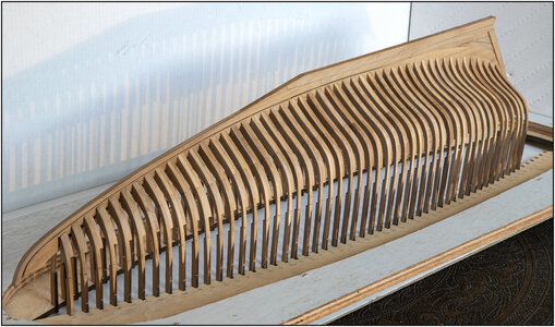
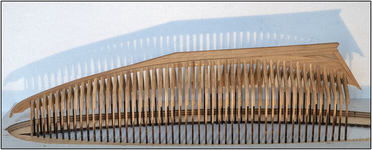
After a small week of cutting, filing, sanding and polishing, finally finish the 49 main frames:
089 Spanten 1-49.jpg
There are now some small differences in the spacing between the frames, mainly visible on the waterline. The temporary spacers will adjust them as soon as the frames are glued together.

Some playing with the light:
090 Spanten 1-49.jpg

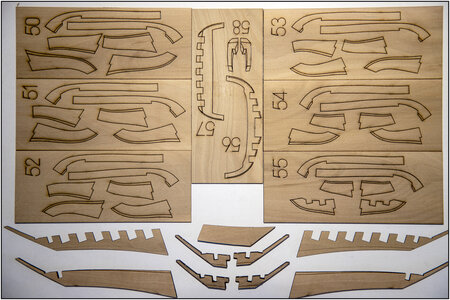
And collected all the parts for the stern:
091 Parts Achter.jpg

According to the manual, I should now attach the parts #19/#65 to the keel. I use a slightly different approach.
Of course assembling the half frames.
I will take some pictures from my steps. It comes down to some parts glueing and further dry fit, where I can grab, fit and view everything around.
Regards, Peter
 
Last edited:
After a small week of cutting, filing, sanding and polishing, finally finish the 49 main frames:
View attachment 231441
There are now some small differences in the spacing between the frames, mainly visible on the waterline. The temporary spacers will adjust them as soon as the frames are glued together.

Some playing with the light:
View attachment 231443

And collected all the parts for the stern:
View attachment 231444

According to the manual, I should now attach the parts #19/#65 to the keel. I use a slightly different approach.
Of course assembling the half frames.
I will take some pictures from my steps. It comes down to some parts glueing and further dry fit, where I can grab, fit and view everything around.
Regards, Peter
Looking great Peter! You are almost ready to glue into the jig and start internal framework! ;)
 
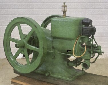
A present for you my friend, as I can see you adding this! ;) The motor that was used on the windlass!
It's too late for me to add this detail, but it would have been fun to scratch build. :)
View attachment 231530
Ca Chug. . . Ca Chug. . . Ca Chug, Chud, Chug . . . Po;p!!! Roar!!!!!!! Sputter. . . " "*** forgot to fill her up!" Redface Rich
 
Back
Top