YUANQING BLUENOSE - Peter Voogt [COMPLETED BUILD]

But only if it doesn't upset the racing balance. ;) Seriously Peter, like I said on Modelbouwforum (and this is basically also what @Dean62 suggested), your layout looks busy, but very organized and "clean". Pursuing the logical ergonomics as per Dean, makes a lot of sense. Luckily, you have a little more space to work with here.
Thank you for your concern, Heinrich. But nothing comes to the detriment of her elegance!
Because a generator also means an extra exhaust ...... :mad:
Regards, Peter
 
Last edited:
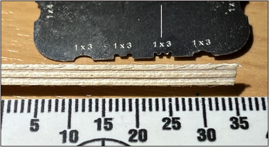
On a rough slat of 1x3 Lime (with some shaving light to accentuate):
AL-ShapersTest.jpg
With the "1x3" with double tooth (see arrow). Nice sharp material.
Of course I could also have sanded the slat nice and smooth ...... It is important to look closely at the grain.
2nd test:
AL-ShapersTest2.jpg
It's soft wood. With harder wood I think it will be even sharper.
For me: they are useful.
Regards, Peter
 
AL's 2 sets of Micro Shapers arrived just in time:
View attachment 274175
Can I try them out right away with the moldings on the walls of the MainCabin.
Made a first start for the frame under the deck beams where the bunks come in and the benches in front. Top and bottom still dry-fit on top of each other.
Regards, Peter
I purchased this same shapers, they work well,, however you have to go slow and make multiple passes. And even then you have to clean up the pieces with a file or sandpaper depending on the wood type. ;)
 
You're definitely spoiling him!
Due to the nature of Peter's build, it requires that kind of detail and precision! I modeled a ships wheel and anchors to use on my ship, which I shared. But I also modeled a windlass motor for Peter to use, because I know he will be adding that detail as well. And the steering mechanism within the steering box also needs to be done, so that can be included. I know that if Peter had to scratch build that, he is very capable! But if I can help provide quality models to be used, then that reduces his work. Plus I enjoy it, and Peter is my friend. ;)
 
Due to the nature of Peter's build, it requires that kind of detail and precision! I modeled a ships wheel and anchors to use on my ship, which I shared. But I also modeled a windlass motor for Peter to use, because I know he will be adding that detail as well. And the steering mechanism within the steering box also needs to be done, so that can be included. I know that if Peter had to scratch build that, he is very capable! But if I can help provide quality models to be used, then that reduces his work. Plus I enjoy it, and Peter is my friend. ;)
And not to forget our other friend Henk @Henk Liebre : and he has a friend with a quality printer. And that friend lives just a few miles from where I live. So, it’s s small world from Missouri City in Texas to Woudrichem in Noord-Brabant. :)
In conclusion: you don’t need to know and have everything: you must know and must have friends! and therefore is the SoS!
 
The start of the steering mechanism...
First the saga drawings...
1638920997253.png

The current mechanism model...
1638921032498.png

And in the assembly using the YQ steering box dims...
1638921155157.png

There is a lot of adjustments that still needs to occur. Peter and me are working together to make that happen! ;)
It is looking promising!
 
New insights:
Now that I'm working out the Cabin and seeing more and more details, I first have to do something in between.
In the Saga drawing you could see that towards the back, the space is open and the floor continues.
You can also see a part of the tube through which the rudder runs. That tube is logical, otherwise the splashing water or if the boat takes deep water at the rear, this water can run through the hole in the hull on the low deck.

First made some extra floor beams to extend the spacer floor. From the waste of the under floorbeam sheets:
View attachment 272980
Can't see very well, but they have a bit of coverage.

The box made to the dimensions of the hole in the keel beam and frames:
View attachment 272981

The connection angle on the keel has been made to fit with the help of 2 fitting battens:
View attachment 272982

Installed the floor beams, the tube and the planks:
View attachment 272983

Through the hole you look straight at the slanted toe at the end of the keel beam. That hazy dark block:
View attachment 272984

Then I can now start customizing the mold for the inner lower walls that run under the deck beams.
Regards, Peter
This is getting interesting!
 
Due to the nature of Peter's build, it requires that kind of detail and precision! I modeled a ships wheel and anchors to use on my ship, which I shared. But I also modeled a windlass motor for Peter to use, because I know he will be adding that detail as well. And the steering mechanism within the steering box also needs to be done, so that can be included. I know that if Peter had to scratch build that, he is very capable! But if I can help provide quality models to be used, then that reduces his work. Plus I enjoy it, and Peter is my friend. ;)
Well, given the quality of his build, his creativity, the learning experience and the surprises he so freely and generously gives us, Peter only deserves the best, so yeah, go ahead and spoil him, but just a little. :D
(And please, don't wake up that darn Lion of yours!) ;)
 
The start of the steering mechanism...
First the saga drawings...
View attachment 274217

The current mechanism model...
View attachment 274218

And in the assembly using the YQ steering box dims...
View attachment 274219

There is a lot of adjustments that still needs to occur. Peter and me are working together to make that happen! ;)
It is looking promising!
What's the superlative step for terrific? Terrificer, terrificist?
I wonder what would happen if the three of you, Henk Liebre, Peter Voogt and you, joined forces and do a build together, long distance. Now that would be a show to watch!

PS You already did the kinematics on the steering mechanism?
 
After looking at different options, I think I'll go for the more sober version. Also seen this sketch from The Saga I showed earlier:
View attachment 273463
Just a rectangular room with 2 bunks on either side. The cross-sectional model of the Nova-Scotia builders has that too.

I do like the separate room for the Captain. Then this could be the format:
View attachment 273464
All this is in the upper part of the hull. In order to keep a view of the interior, 2 walls and the roof will be opened up.
To starboard:
-the Captains Cabin with door and private bunk under the deck beams. In the completion, a private sink and a writing table with chair against the wall. On the walls the necessary cupboards and shelves;
-next to the Captains Cabin a 2nd bunk under the deck beams with the bench with storage spaces in front of it.
Against the partition wall with the FishHold a table. There is another bench on the starboard side.
The block of wood is the position of the stove.
View attachment 273465
To port:
-2 bunks under the deck beams with the continuous bench with storage spaces in front of it.
Against the back wall is the staircase with side partitions.
A partition wall will be built under the deck beam against which the stairs abut. With access hatch to the space behind it. In front of the wall there is also a continuous bench with storage spaces.

I will use this as a starting point. But ......Things can change during construction. ;)
Regards, Peter
I love your playing around with ideas, based on the little information you have available.
Right now I'm not entirely certain which parts of the main cabin attach to the lower hull and which parts will be fixed to the upper hull. All interior parts to the lower hull for visibility and the cabin itself to the upper hull (which seems logical)?
 
And not to forget our other friend Henk @Henk Liebre : and he has a friend with a quality printer. And that friend lives just a few miles from where I live. So, it’s s small world from Missouri City in Texas to Woudrichem in Noord-Brabant. :)
In conclusion: you don’t need to know and have everything: you must know and must have friends! and therefore is the SoS!
I completely agree

I took over the translation work from Dean at the beginning of this year, so that he could continue working before the deadline of his BN
Dean sends me the print files
I prepare them with the software I have for 3D printing
I help my other friend modeler for info for his sub
He prints the 3D workpieces
3 D prints to Peter and later to Canada for another SOS member
If necessary I call on Peter as a helpline for questions
And so everyone does something for each other

And what think what, am writing this, the radio is on, and it's playing

Stevie Wonder & Dionne Warwick - That's What Friends Are For
In this way, all of you has an overview of the entire logistics line.
The windlass motor has yet to be printed. but we don't want to burden the print friend too much. When the steering mechanism is ready, it goes to the Printer in one shift. So economical. As much in terms of printing as driving between our 3 hometowns.
Regards, Peter
 
What's the superlative step for terrific? Terrificer, terrificist?
I wonder what would happen if the three of you, Henk Liebre, Peter Voogt and you, joined forces and do a build together, long distance. Now that would be a show to watch!
Thanks for the compliment Johan,

However I do not yet have the skills and experiences of Dean and Peter
I have yet to see the railing will fall at the keel soon, that will be a thing

Regards

Henk
 
I love your playing around with ideas, based on the little information you have available.
Right now I'm not entirely certain which parts of the main cabin attach to the lower hull and which parts will be fixed to the upper hull. All interior parts to the lower hull for visibility and the cabin itself to the upper hull (which seems logical)?
The cabin is complete in the upper part. But visible through a half roof and 1,5 open wall.
Hopefully in a few day some results …..
 
Last edited:
Back
Top