YUANQING BLUENOSE - Peter Voogt [COMPLETED BUILD]

Henk, Peter,

This morning Henk and I met in person and also discussed this intriguing topic. So once home again I checked to see whether or not the "Saga" held some clues and sure it does. Please keep in mind the "Saga" describes the BN II, meaning that the BN I might have a different configuration.
Pages 108/109 give a pictorial indication that the hull's side planks covered the ends of the stern planks, see attached picture.
I'm not certain the wake turbulence argument is driving that configuration, I suspect that that area may be characterized as being wet, terribly wet and the turbulence is just adding to the agony of water intrusion...
On another Bluenose build I've seen the side planks being cut at the stern and the stern planks overlapping the side planks.
I guess it's AL-FI time again, it's your decision; what do you feel comfortable with and what do you want to present.

Have fun!

Johan

View attachment 284721
Thanxs, Johan. I know the drawing. And indeed, this is the FI-part of my AL-FI. ;)

And a perhaps strange question from me: Why are the planks on the bow not up to the front on the sides of the keel? Why locked up there in the rabbet? And till the deadwood also let in?
At the stern 2 parts of planks comes together. Then there must be choosen for a solution.

But one more thing: on the now oiled planks I did something unorthodox with the treenails. Who knows, may say. Then I tell my FI about that too.

That reminds me of my work, when I switched to the analysis part of my work. That was new for our service and had to be developed.
We started making relation-diagrams to provide insight into the connections between the evidence traces on different crime scenes. This also brought us into contact with the tactical analysts. We did it very differently from them, who are known as the specialists and have been doing it their way for years. And they found ours more understandable. AL-FI was unknown at that time, but deep inside of me ..........

That naughty boy is still inside of me. ;)
Regards, Peter
 
And a perhaps strange question from me: Why are the planks on the bow not up to the front on the sides of the keel? Why locked up there in the rabbet? And till the deadwood also let in?
At the stern 2 parts of planks comes together. Then there must be choosen for a solution.
First off, I'm not an experienced shipbuilder, so at best what I have to offer is a best educated guess.
Extending the planks in front of the keel either results in sharp edged planks or in a very funny lapjoint.
The edge formed by the sharp edged planks is very prone to impact damages and also very difficult to protect against the elements. Also the trenails connecting the LH- with the RH-planks might cause some edge distance issues, by not having sufficient "meat" to be placed sufficiently robust. Another issue could be that not enough clamping force exists between the LH- and RH-planks, causing the planks to gap at the most critical location. Another issue and not all together unimportant, is the watertightness of the hull. I understood that one of the functions of the rebate is to improve the watertightness of the hull, by providing more surface area to seal the planks.
My idea is that a configuration of joined LH- and RH-planks might require a protection- annex connection profile (possibly u-shaped) to counteract (some of) the described issues.
At the stern one has to choose between two evils. Whatever you choose, water ingress will be an issue.
Maybe someone else on SOS has a better understanding of shipdesign and shipbuilding, so I'm eager to learn from an expert...
 
That reminds me of my work, when I switched to the analysis part of my work. That was new for our service and had to be developed.
We started making relation-diagrams to provide insight into the connections between the evidence traces on different crime scenes. This also brought us into contact with the tactical analysts. We did it very differently from them, who are known as the specialists and have been doing it their way for years. And they found ours more understandable. AL-FI was unknown at that time, but deep inside of me ..........
This in turn reminded me of the survival bias topic from WWII, where people sought to better protect/reinforce the areas of aircraft, prone to battle damage until a very clever lad observed that one had to carefully look at the areas, showing little or no damage from returning aircraft, because he suspected that aircraft receiving damage in those areas did not return...
https://worldwarwings.com/the-statistics-that-kept-countless-allied-fighter-planes-in-the-sky/
 
First off, I'm not an experienced shipbuilder, so at best what I have to offer is a best educated guess.
Extending the planks in front of the keel either results in sharp edged planks or in a very funny lapjoint.
The edge formed by the sharp edged planks is very prone to impact damages and also very difficult to protect against the elements. Also the trenails connecting the LH- with the RH-planks might cause some edge distance issues, by not having sufficient "meat" to be placed sufficiently robust. Another issue could be that not enough clamping force exists between the LH- and RH-planks, causing the planks to gap at the most critical location. Another issue and not all together unimportant, is the watertightness of the hull. I understood that one of the functions of the rebate is to improve the watertightness of the hull, by providing more surface area to seal the planks.
My idea is that a configuration of joined LH- and RH-planks might require a protection- annex connection profile (possibly u-shaped) to counteract (some of) the described issues.
At the stern one has to choose between two evils. Whatever you choose, water ingress will be an issue.
Maybe someone else on SOS has a better understanding of shipdesign and shipbuilding, so I'm eager to learn from an expert...
Many books and treatises have been written about it. As amateur modellers, let's just have fun.
Regards, Peter
 
The full planking of the port side is now next.
This is YQ's drawing:
586 PostPlanks.jpg

Jenson has in The Saga only drawn part of the possible planking of the original BN:
587 PostPlanks.jpg

From the BN-II he has signed this:
588 PostPlanks.jpg

In 'Witch in the Wind', De Villiers writes on p. 62:
"The longest plank on the Bluenose's 143-foot frame was about 30 feet. They tapered, somewhere around 12 inches amidships, down to 7 inches at the bow and stern. They were in the steam box before fastening."
So he doesn't write about 'inserters' or 'stealers' etc.

Maybe a bit of stubbornness comes into play here, but for the garboard plank and the 2nd plank I use a whole plank that I let run into a point in the rabbet:
589 PostPlanks.jpg
Just a visual aspect.

Now I'm going to measure, calculate and draw how I will continue to plan the hull. Where the visual aspect is in the foreground.
I let you know .......
Rergards, Peter
 
There is always a 1st step in a next chapter.
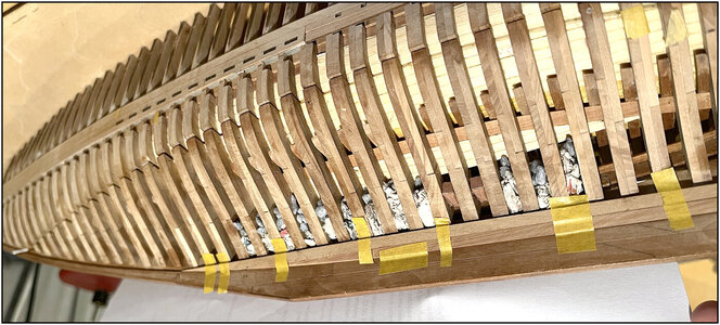
Here the 1st part of the garboard plank glued in:
590 PostPlanks.jpg
The pieces of newspaper are padding at the ballast. That saved stones. ;)

When planking the port side I use the same principles as on starboard: planks of 'max. 30 feet' - max. 12.6 cm. They fall max. over 12 frames. But there are also shorter ones, because I plank in wild context.
I cut the parts from the kit to length and mix them together.
With 'fill' planks that I cut from a random planks.

The only thing that bothers me a bit are the 2 large parts of the bulwark. The upper - front part runs over 34 frames. With some imitation plank connections, but the drawing of the wood with the wood grain continues. I had considered mixing the port and starboard parts, but decided against it.

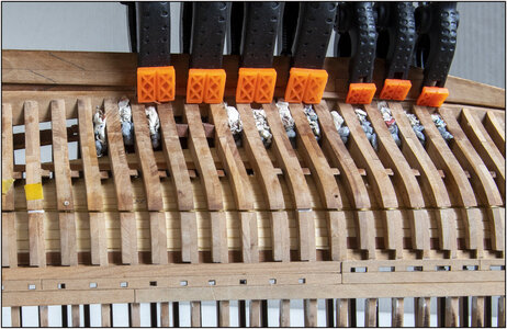
The garboard stroke and the 2nd row have been applied:
591 PostPlanks.jpg
I immediately marked the location of the treenails. Because now I have the frames next to the plank in view. Maybe I will also provide some rows with the treenails in the meantime. Then I don’t have to do everything at once. Then the sensitive finger can recover in the meantime.

On 5 frames I glued strips of mm-paper in the space that still needs to be planked. Now I can calculate how many planks I need in 5 positions. And whether it is feasible to only plank with bevelled planks without stealers.
Regards, Peter
 
Last edited:
C'è sempre un primo passaggio in un capitolo successivo.
Qui la prima parte della tavola del garboard incollata:
View attachment 285066
I pezzi di giornale stanno riempiendo la zavorra. Che ha salvato pietre.;)

Quando si fascia a babordo utilizzo gli stessi principi di dritta: tavole di 'max. 30 piedi' - max. 12,6 cm. Cadono al massimo oltre 12 fotogrammi. Ma ce ne sono anche di più brevi, perché io planco in un contesto selvaggio.
Ho tagliato le parti del kit a misura e le mescolo insieme.
Con assi di "riempimento" che taglio da assi casuali.

L'unica cosa che un po' mi infastidisce sono le 2 grandi parti della murata. La parte superiore - anteriore corre su 34 telai. Con alcune finte connessioni della tavola, ma il disegno del legno con la venatura del legno continua. Avevo pensato di mescolare le parti di babordo e di dritta, ma ho deciso di non farlo.

Sono state applicate la corsa del garboard e la 2a fila:
View attachment 285065
Ho subito segnato la posizione delle unghie degli alberi. Perché ora ho le cornici vicino alla tavola in vista. Forse nel frattempo fornirò anche alcune file con le unghie degli alberi. Allora non devo fare tutto in una volta. Quindi il dito sensibile può nel frattempo riprendersi.

Su 5 telai ho incollato strisce di carta da mm nello spazio che deve ancora essere placcato. Ora posso calcolare quante plance mi servono in 5 posizioni. E se è possibile eseguire solo listoni con listelli smussati senza ladri.
Saluti, Pietro
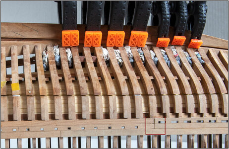
Ciao Pietro , scusami ,ti allego una Tua foto,lo stacco dei due corsi di fasciame rimangono così, esteticamente danneggia il bel lavoro che stai facendo, scusami
 

Attachments

  • 590 PostPlanks.jpg
    590 PostPlanks.jpg
    450.7 KB · Views: 10
Hi Pietro, sorry, I am attaching a photo of you, the detachment of the two strakes remain like this, aesthetically it damages the good work you are doing, sorry
Thats correct, Frank. But that are the provided parts from YQ. They made there a imitation plank joint. And there under must be attached a single plank.
Now it is high-lighted, but did you have noticed the same on the other side?
So, when the BN is ready and someone is pointing this to me, that person gets from me a ‘Bossche Bol’.
Regards, Peter
 
Last edited:
Esatto, Frank. Ma queste sono le parti fornito da YQ. Lì hanno realizzato un'imitazione della tavola. E lì sotto deve essere attaccata un'unica tavola.
Ora è evidenziato, ma hai notato lo stesso sull'altro lato?
Quindi, quando il BN è pronto e qualcuno me lo indica, quella persona riceve da me una "Bossche Bol".
Saluti, Pietro
in verità non ho visto l'atro lato , si ora è molto peggio dell'altro , io lo rifarei ma, decidi Tu
 
By having the strips of mm paper follow the frames, I was able to get started creating a projected surface to be planked.
First scanned a 1:1 drawing of YQ in parts and pasted together in Photoshop.
Then separate the top and bottom. And on the 5 places where I had stuck the mm strips, slid them at the right distance. Also made paper molds on the front and back. These were also scanned and pasted into the drawing.
Then you get this visually distorted image, with curves drawn apart and straight:
592 PortPlanks.jpg
But it is the projected surface that needs to be planked.

After some calculation and drawing I would need 20 planks of 4.1 mm to fill the widest part. YQ's planks are 4.2 mm.
Then if I wanted to get continuous strips, I would have to chamfer them towards the front to 2.8 mm. All in all, a lot of work with a strange image.

That's why I decided to follow YQ's schedule. With 2 recessed planks at the back to fill the running width:
593 PortPlanks.jpg
Because it is true that I then come up +/- 8.0 mm short at the back. They come on the 2 strips that I have already applied to my BN. All in all a well-done design of YuanQing @yqmodel !

Then did some math. Because I do want to have a plank in the middle of the saw cuts where it runs over several frames. In order not to end up with a strip of wood of one mm over several frames.
Then I have to cut the first 4 strips to 4.0 mm.
10 battens sawn in 2 stages to 4.0 mm. I gave the saw edges a small chamfer. So that I exaggerated this form: /___\. Because then I can get them nice and tight against each other in the curve of the hull. If I keep the planks |___|, I will give a cracks on the outside. The lasered planks from YG already have a small chamfer due to the laser. That was taken as a starting point.

Started from above and front with the cut to length strips falling over 12 frames:
594 PortPlanks.jpg
And I was also (until now) been able to maintain a regular pattern of a plank connection every 3 frames, which comes back every 4 strips.
First I plan further up to the seam, and then start the further sawing experiment again. But I will do that strip by strip.
Regards, Peter
 
Last edited:
By having the strips of mm paper follow the frames, I was able to get started creating a projected surface to be planked.
First scanned a 1:1 drawing of YQ in parts and pasted together in Photoshop.
Then separate the top and bottom. And on the 5 places where I had stuck the mm strips, slid them at the right distance. Also made paper molds on the front and back. These were also scanned and pasted into the drawing.
Then you get this visually distorted image, with curves drawn apart and straight:
View attachment 285657
But it is the projected surface that needs to be planked.

After some calculation and drawing I would need 20 planks of 4.1 mm to fill the widest part. YQ's planks are 4.2 mm.
Then if I wanted to get continuous strips, I would have to chamfer them towards the front to 2.8 mm. All in all, a lot of work with a strange image.

That's why I decided to follow YQ's schedule. With 2 recessed planks at the back to fill the running width:
View attachment 285658
Because it is true that I then come up +/- 8.0 mm short at the back. They come on the 2 strips that I have already applied to my BN. All in all a well-done design of YuanQing @yqmodel !

Then did some math. Because I do want to have a plank in the middle of the saw cuts where it runs over several frames. In order not to end up with a strip of wood of one mm over several frames.
Then I have to cut the first 4 strips to 4.0 mm.
10 battens sawn in 2 stages to 4.0 mm. I gave the saw edges a small chamfer. So that I exaggerated this form: /___\. Because then I can get them nice and tight against each other in the curve of the hull. If I keep the planks |___|, I will give a cracks on the outside. The lasered planks from YG already have a small chamfer due to the laser. That was taken as a starting point.

Started from above and front with the cut to length strips falling over 12 frames:
View attachment 285659
And I was also (until now) been able to maintain a regular pattern of a plank connection every 3 frames, which comes back every 4 strips.
First I plan further up to the seam, and then start the further sawing experiment again. But I will do that strip by strip.
Regards, Peter
Looking good so far. ;)
This was one of the easiest hulls I have planked! The stern and bow do not have any extreme bends, so almost all flat planking. The taper is very minimal, almost unnecessary. Also minor beveling of the sides, but if you use the taper of the laser, you don’t have to do anything in some areas. Overall, this hull shape is very nice to work with.
Thanxs, Dean. Good to have you back!.
I will see it, working to the bottom / end.
Regards, Peter
 
Looking good so far. ;)
This was one of the easiest hulls I have planked! The stern and bow do not have any extreme bends, so almost all flat planking. The taper is very minimal, almost unnecessary. Also minor beveling of the sides, but if you use the taper of the laser, you don’t have to do anything in some areas. Overall, this hull shape is very nice to work with.
I can't help but wonder whether or not the Bluenose loft was intended to lead to a more or less straight forward hull planking, thus reducing build cost. A second thought on the flow of the lines; it results in a gradual increase of frontal area from the bow to maximum cross-sectional area midships and a gradual decrease of cross-sectional area towards the stern (although not as pronounced), thus giving the hull minimum resistance and generating minimum turbulence in the water.
 
I can't help but wonder whether or not the Bluenose loft was intended to lead to a more or less straight forward hull planking, thus reducing build cost. A second thought on the flow of the lines; it results in a gradual increase of frontal area from the bow to maximum cross-sectional area midships and a gradual decrease of cross-sectional area towards the stern (although not as pronounced), thus giving the hull minimum resistance and generating minimum turbulence in the water.
That’s right, Johan. She was, of course, co-designed for the Fisherman's Races.
This is also apparent from this passage from the Witch in the Wind (pag. 32):
At the same time, William Dennis and his yachting friends were casting about for a way to build a new boat that would be big and strong enough to fish the Banks, and at the same time fast enough to beat anything Gloucester could throw at them - fishing yes, that’s important, but fast was the prime stipulation. They found William Roué to design it for them.
Regards,Peter
 
Last edited:
Thanxs, Johan. I know the drawing. And indeed, this is the FI-part of my AL-FI. ;)

And a perhaps strange question from me: Why are the planks on the bow not up to the front on the sides of the keel? Why locked up there in the rabbet? And till the deadwood also let in?
At the stern 2 parts of planks comes together. Then there must be choosen for a solution.

But one more thing: on the now oiled planks I did something unorthodox with the treenails. Who knows, may say. Then I tell my FI about that too.

That reminds me of my work, when I switched to the analysis part of my work. That was new for our service and had to be developed.
We started making relation-diagrams to provide insight into the connections between the evidence traces on different crime scenes. This also brought us into contact with the tactical analysts. We did it very differently from them, who are known as the specialists and have been doing it their way for years. And they found ours more understandable. AL-FI was unknown at that time, but deep inside of me ..........

That naughty boy is still inside of me. ;)
Regards, Peter

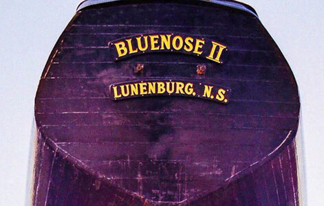
Stumbled on this picture of the BN II, https://www.flickr.com/photos/manfromgladphotos/, page 5
Not that I want to open up the discussion again, but it's kinda nice to know...
529E991C-5B46-4602-A9FA-BD7C84F46D5F.jpeg
 
Back
Top