• Win a Free Custom Engraved Brass Coin!!!
    As a way to introduce our brass coins to the community, we will raffle off a free coin during the month of August. Follow link ABOVE for instructions for entering.

Artesania Latina Anatomy of Lord Nelson’s HMS Victory 1805

You folks doing the lighting amaze me. I guess we can all do it but I am totally intimidated by this. Nicely done.

It may just be the lighting in the photos but are they upside down? The plates were nailed on so there would be dents where the nails were hammered in rather than the appearance of rivet heads.
View attachment 534789
Hey Alan,

Thanks for the reply. That's quite expensive. The work alone is insane. You have my respect! I also bought the kit. Also the roller for the copper foil. I'm going to try it out and then decide whether to buy the copper plates or use the foil. I would be happy to show you a picture of it. As for your photo of the Victory, where did you find it? I'm confused at the moment, because I feel the same way as you do, that the nails were hammered in and thus countersunk and no rivets are visible, but recessed. Or am I wrong?

Best regards
Günther Ship-1
 
that the nails were hammered in and thus countersunk and no rivets are visible,

Hi Gunther
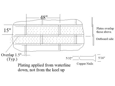
The photo is the USS Constitution, but it is pretty much identical to the description of plating given by Peter Goodwin in The Construction and Fitting of The English Man of War on page 225. After about 1760 the nails were copper with typically 5/32" diameter with 5/16" heads assuming he is correct. Manufacturing limitations apparently were the governing factor in the plate size which was typically 48" X 15" Victory was not coppered until a refit in 1779. I love to see someone model Victory prior to this date with payed bottom, Armstrong cannon and painting other than the Nelson chequer.

Allan
 
Hello Alan,

Thank you very much for your great explanation of the copper panelling.

My dream is to build the Victory before 1779. I would like to build her as she can be seen in the Naval Museum in Greenwich. In other words, as she was in 1765, with the old galleon figurehead and the beautiful stern. Of course, she won't have any copper plating. I'll save that for later, when I build the HMS Victory again. I'm using the Victory from Atesania Latina for the conversion. It's currently the best commercial kit you can get for the money. I already have it in my hobby room.

Of course, I'm going to make a lot of changes and I'm looking forward to any help with the rigging here in the forum. But everything comes after the Athena ... although I'm only just starting on the dinghy.

Best regards
Günther Ship-1
 
No, it’s supposed to be rivet heads
Not prototypical but gives a nice effect. All commercially made copper plates are like that as far as I know
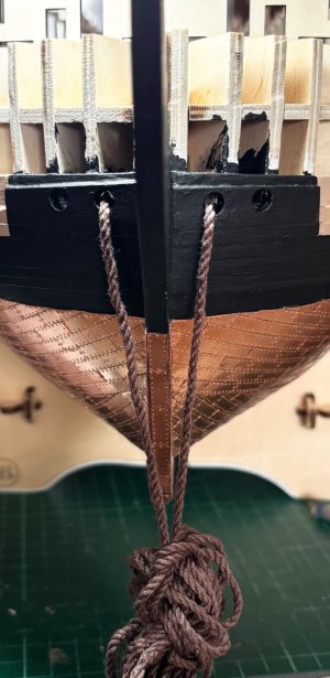
Vanguard and, I think the newest ones from Amati, have etched nail dents rather than the pox like bumps. Hopefully some members know of others as well. Scale is an issue as well so some folks have had more realistic plates by making their own. At the smaller scales, copper paint, scribed lines, and pin holes are another option. Assuming the AL Victory scale is 1:84 the plates should be 14.5mm long X 4.5 mm if they are going to be properly overlapped. If the builder chooses to butt them together they would be about 1/2mm smaller in width and length. If appearance matters, check out the patterns of both brands and how the full size plates were actually done to see which you think is best for your own project.
Allan
From drawings in The Construction and Fitting of the English Man of War by Peter Goodwin
1753958533891.jpeg
 
Vanguard and, I think the newest ones from Amati, have etched nail dents rather than the pox like bumps. Hopefully some members know of others as well. Scale is an issue as well so some folks have had more realistic plates by making their own. At the smaller scales, copper paint, scribed lines, and pin holes are another option. Assuming the AL Victory scale is 1:84 the plates should be 14.5mm long X 4.5 mm if they are going to be properly overlapped. If the builder chooses to butt them together they would be about 1/2mm smaller in width and length. If appearance matters, check out the patterns of both brands and how the full size plates were actually done to see which you think is best for your own project.
Allan
From drawings in The Construction and Fitting of the English Man of War by Peter Goodwin
View attachment 535035
Hi Allan
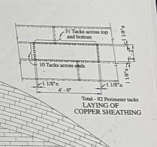
This is from the book “HMS Victory, her Construction, Career and Restoration “ by Alan McGowan. I used this as a rough guide for installing my plates. If you’ve read my original post on this, you will know that I’m aware of the scale issue. Using these plates was my personal preference over the supplied self adhesive tape. I’ve seen many photos of other completed Victory models using these or similar plates, all showing the “pox” bumps as you call them. I like to do a nice job but on some things I’m not a rivet counter, excuse the pun :D

IMG_2681.jpeg
 
Last edited:
Hello Alan,

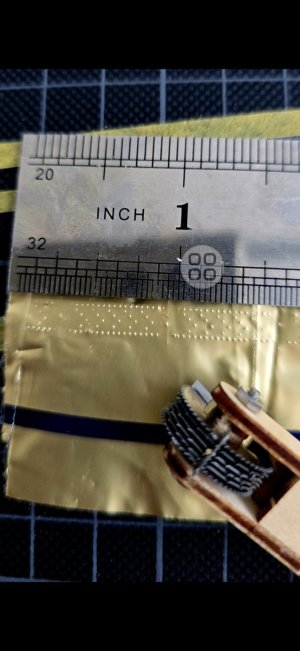
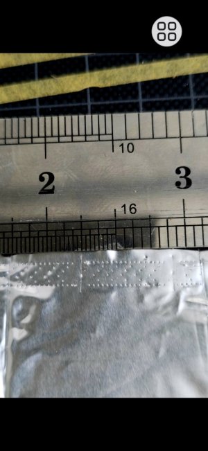
thank you very much and very good picture of the copper plating. I have some pictures of a sample of the AL roller to imitate the nailing. I think it is very close to the one above. What do you think? However, the dimensions are not correct based on your calculation. So the aluminium roller is too big.

Best regards
Günther Ship-1
Nagelung Kupfer.jpg Nagelung Kupfer2.jpg
 
Hi Allan
This is from the book “HMS Victory, her Construction, Career and Restoration “ by Alan McGowan. I used this as a rough guide for installing my plates. If you’ve read my original post on this, you will know that I’m aware of the scale issue using these plates was my personal preference over the supplied self adhesive tape. I’ve seen many photos of other completed Victory models using these or similar plates, all showing the “pox” bumps as you call them. I like to do a nice job but on some things I’m not a rivet counter, excuse the pun :D

View attachment 535039
Hey Alan,
your work is very very good. Iam a Fan of your built. Sorry for the discuss of the Coppers.:DThumbsup
Cheers
Günther
 
Hello Alan,

thank you very much and very good picture of the copper plating. I have some pictures of a sample of the AL roller to imitate the nailing. I think it is very close to the one above. What do you think? However, the dimensions are not correct based on your calculation. So the aluminium roller is too big.

Best regards
Günther Ship-1
View attachment 535040 View attachment 535041
Hi Gunther
Sorry for late reply to this, but yeah, the roller seems to make the plates longer than they should be. Also, if my drawing from the book is correct, you should not have nails in the middle of the plate either. But at the end of the day it’s your model for you to decide which way you want to go
Regards
Alan
 
Instructions video #23 completed

I now tackle (excuse the pun) the blocks and tackles
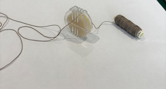
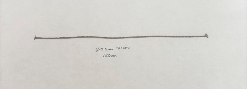
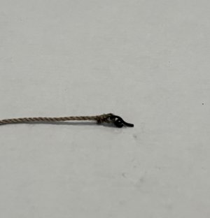
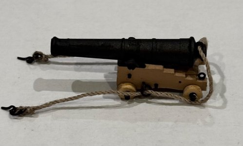
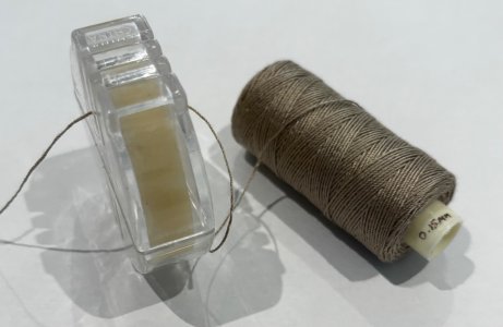
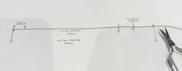
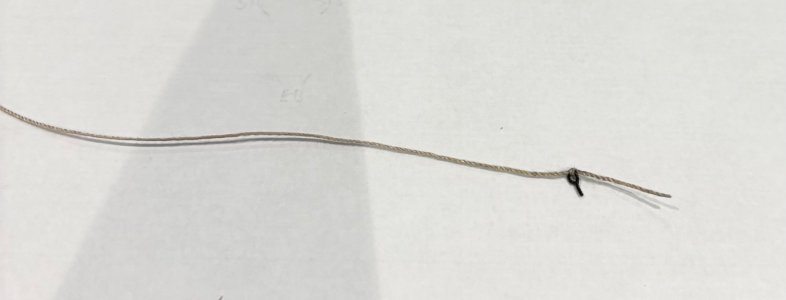
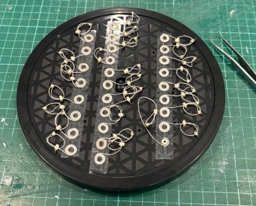
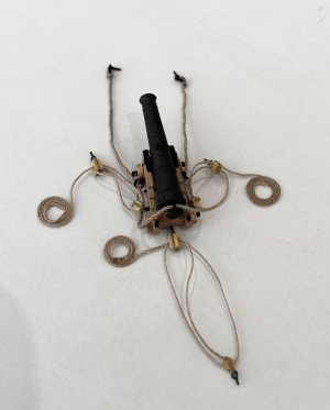
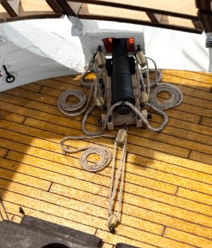
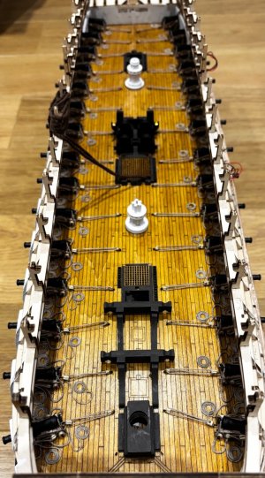
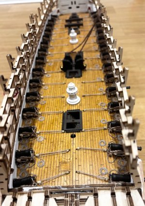
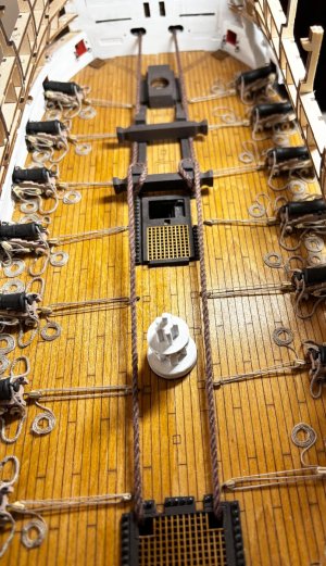
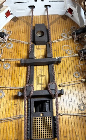
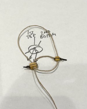
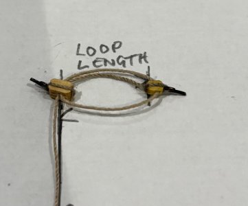
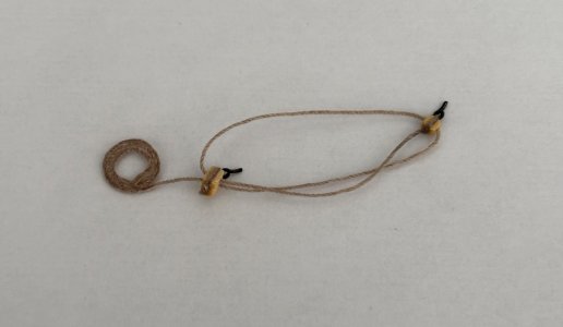
As before I adopted production line mode, and rigged all 30 cannons before placing any on deck. I made myself a little measurement rig so that all threads etc would be approximately the same. Before cutting the threads I pull them through bees wax, which helps stop them fuzzing. I decided not to follow the instructions and made rope coils on the ends of the tackle ropes, a lot more work but I felt it was worth it.
Once I started to rig the cannon it became clear that the 0.5mm holes we are told to drill in the back of the gun carriages are not big enough to take the pin of part EB, the pre-drilled holes in the side of the carriages should have been a clue, so it follows that the holes drilled around the gun ports in video #17 would not be large enough either, so I had to revisit the gun port holes and enlarge them, not so easy with the capstans and other deck fittings now in place. So if you are doing this kit and haven’t reached video #17 yet, ignore the instruction to drill 0.5mm holes and drill them 0.7mm instead, likewise the holes in the back of the gun carriages.

IMG_2967.jpeg

IMG_2969.jpeg

IMG_2971.jpeg

IMG_2972.jpeg

IMG_2978.jpeg

IMG_2980.jpeg

IMG_2981.jpeg

IMG_2982.jpeg

IMG_2983.jpeg

IMG_2984.jpeg

IMG_2985.jpeg

IMG_3028.jpeg

IMG_3038.jpeg

IMG_3044.jpeg

IMG_3045.jpeg

IMG_3074.jpeg

IMG_3075.jpeg

IMG_3076.jpeg

IMG_3077.jpeg
 
Hi Alan, I am also up to this stage of making the block and tackles. My question is did you make the small wooden 'block' parts yourself as I cannot seem to find these parts in the kit. How did you fashion them? Thanks so much. Love your work. Tony M
 
Hi Tony
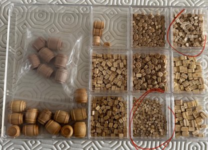
All the wooden blocks are located in one of the clear plastic parts containers
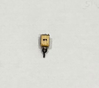
I didn’t think much of the quality of the smallest single hole blocks, some didn’t have holes in them and I found I had to enlarge the holes to pass the thread through them even using a “Big Eye” needle

IMG_3082.jpeg
 
Hey Alan,

great work. That looks fantastic. beautifully clean work. I still have the Vici lying around. But it will have to wait. really very nice. Question: Where did you get the part with the beeswax? I think it's great and would love to have it too.

Best regards

Günther Ship-1
 
Hey Alan,

great work. That looks fantastic. beautifully clean work. I still have the Vici lying around. But it will have to wait. really very nice. Question: Where did you get the part with the beeswax? I think it's great and would love to have it too.

Best regards

Günther Ship-1
Can’t remember exactly where I got it, was a long time ago, but as RussF said, any sowing shop will do

IMG_3092.jpeg
 
Back
Top