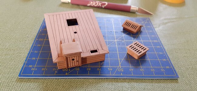
Wow …. It took a lot of perseverance, but the time invested will soon pay off.
Now time for things pleasing to the mind and the eye.
Now time for things pleasing to the mind and the eye.
 |
As a way to introduce our brass coins to the community, we will raffle off a free coin during the month of August. Follow link ABOVE for instructions for entering. |
 |
 |
The beloved Ships in Scale Magazine is back and charting a new course for 2026! Discover new skills, new techniques, and new inspirations in every issue. NOTE THAT OUR FIRST ISSUE WILL BE JAN/FEB 2026 |
 |

I think it's a universal thing...

Good heavens! Now that's what's being called "progress".... How many people have you working on your build?

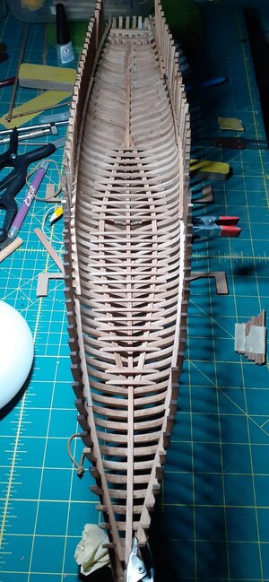
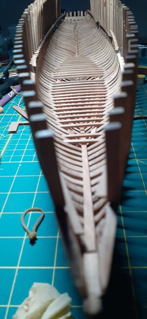
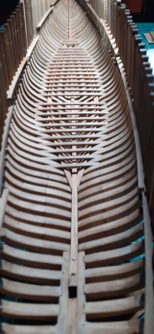

Very challenging to see your build without the jig. Your are making a great progress. Now your pre-sanding and get rid of the char of the different beams pays out.
Regards, Peter
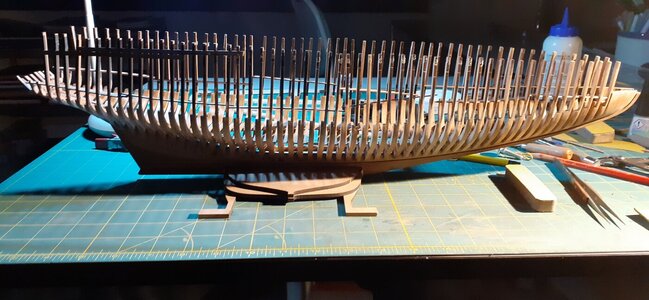

Piero that looks great! I am just amazed at the speed with which you work. Maybe you should pay Maranello a visit with some advice for the 2022 season!
If you are not using the jig for the upper frames, then there is no reason to have the extra height. You can go ahead and trim them close to the final height. Which is…deck beam height + deck height + distance from the bottom of the scuppers on the bulwarks to the top of the bulwarks = height from the step (transition from two frames to one). Add about 5mm safety margin to that and cut off the rest. Just a suggestion to make working inside easier.Indeed! I prefer to work with a free field around the model. It is important to keep the same distance between the frames but I followed your suggestion by placing the spacers without glue.
View attachment 285052

I think I'm gonna find myself a shelter where I can take cover and wait for this storm to be over.Good evening guys, or good morning depending on where you are around the globe!
The first level deck is finished!
View attachment 285042
I have seen on some build logs that some planks have been placed and I believe that before proceeding with the main deck I will put them too. Some, alternate with respect to the upper deck.
View attachment 285043View attachment 285044
See you soon (next deck ... probably)

Was wondering that as well. Sound advice.If you are not using the jig for the upper frames, then there is no reason to have the extra height. You can go ahead and trim them close to the final height. Which is…deck beam height + deck height + distance from the bottom of the scuppers on the bulwarks to the top of the bulwarks = height from the step (transition from two frames to one). Add about 5mm safety margin to that and cut off the rest. Just a suggestion to make working inside easier.

One of the purposes of the jig, at least to me, is to have some control of the contours of the hull.Indeed! I prefer to work with a free field around the model. It is important to keep the same distance between the frames but I followed your suggestion by placing the spacers without glue.
View attachment 285052

If you are not using the jig for the upper frames, then there is no reason to have the extra height. You can go ahead and trim them close to the final height. Which is…deck beam height + deck height + distance from the bottom of the scuppers on the bulwarks to the top of the bulwarks = height from the step (transition from two frames to one). Add about 5mm safety margin to that and cut off the rest. Just a suggestion to make working inside easier.

I think I'm gonna find myself a shelter where I can take cover and wait for this storm to be over.
As far as I can see there's definitely no good food, no good drink and no good .... for you in the near future.
Be sure to leave the proper height needed above the deck beams. That would be the deck board thickness plus the bulwarks (from bottom of scuppers to top of bulwarks. Then you can add a few to that.You're right Dean! I was thinking to do that, I wanna just fit the deck beam support then will cut the frames a few millimiter higher for safety margin.

Looking at your jig-less set-up again, I couldn't help but wonder how you get the frames positioned correctly. The frames are oriented perpendicular to the waterline plane, the lower keel surface on the other hand has a small angle (alpha) (and is not parallel) to the waterline plane. Your keel clamping now gives you your reference plane, nothing wrong with that, which means that the frames have to be positioned with an angle 90 degrees minus alpha on the fwd side of the frames. (Measuring on the aft side it would be 90 degrees plus alpha.) Do you rely completely on the notches in the frames and the keel ánd the equidistant frames pacing, using spacers, or do you have other measures in place to ensure proper frame/keel alignment?Indeed! I prefer to work with a free field around the model. It is important to keep the same distance between the frames but I followed your suggestion by placing the spacers without glue.
View attachment 285052

Looking at your jig-less set-up again, I couldn't help but wonder how you get the frames positioned correctly. The frames are oriented perpendicular to the waterline plane, the lower keel surface on the other hand has a small angle (alpha) (and is not parallel) to the waterline plane. Your keel clamping now gives you your reference plane, nothing wrong with that, which means that the frames have to be positioned with an angle 90 degrees minus alpha on the fwd side of the frames. (Measuring on the aft side it would be 90 degrees plus alpha.) Do you rely completely on the notches in the frames and the keel ánd the equidistant frames pacing, using spacers, or do you have other measures in place to ensure proper frame/keel alignment?
Using the jig, I rely on the notches in keel and frames to ensure location, where as the jig provides me with the means to ensure proper frame orientation, using spacers to keep the frames equidistant slightly below deck levels.
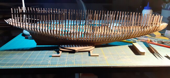

Hello Piero,I know Johan, the jig test was made specifically to overcome all the calculations you made (90° ± xyz). And that's it!
If you look at the last pic, with the keel flat, the frames are slightly pointed towards the bow and if I raise it by xyz° I will have the waterline exactly orthogonal to the frames. When I decided to delete the jig I did exactly the calculations you did, and the xyz angle is almost 5°.
View attachment 285318
Here I raised and fixed the keel of the degrees necessary to have the waterline parallel to the flat, and I started to assemble the frames, one by one, using a 90° square to obtain orthogonality. Very simple and quick to make!


