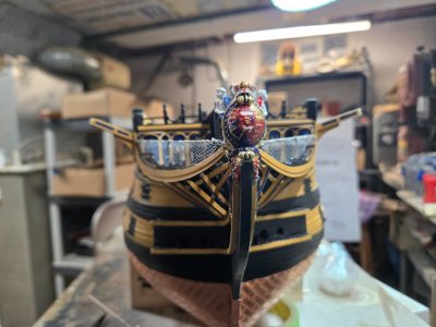
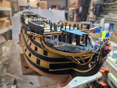
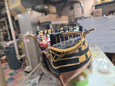
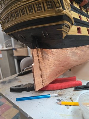
H.M.S. Victory by Caldercraft - Build Log

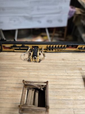
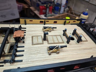
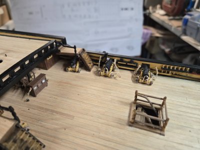
I have to rig 4 regular size cannons and the 2 longer cannons, plus the 2 carronades.
There are 2 under the steps, which I will add breech lines and the back tackle only.

I have added the breech lines for the 8 guns and have been trying to work on the tackles.

I did 2 and have temporarily installed them to the bulwark walls. The tackle work is just sad.
I am going to take another stab at it using Kurt's tutorial...I don't hold much hope though.

My biggest problems are my fat fingers, 62 year old hands that shake and the inability to keep things still while I tie things.
I've seen builders pin the blocks to styrofoam, but these blocks are SO SMALL and I don't really have any pins small enough. I do have a new batch of drill bits and may try that.

As Kurt says, this is a SLOW, ZEN process. It's Christmas time as I post this, so I'll turn on the 24 hour Christmas music station and try again!!!!!
(yeah, I know, but I always feel like I owe it to Christmas to play their music this month!!!!)

20241202_212133.jpg

20241204_173106.jpg

20241204_173111.jpg
 
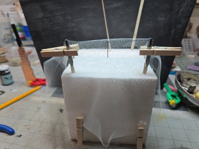
Finally, I took another stab at the first of the nettings on the boat.

I rigged up a little jig to hold the railings for the bow and weighted them with little clothespins.

I think used a needle and carefully sewed the tops across. I added some CA glue every few stitches to keep things tight...but not so tight that it would bunch the fabric.

After, I cut away the excess and glued them in place.

These were easy because I was able to remove the structure while I worked on it. When I move to the hammocks, I'm going to have to do all this while they are on the boat. Hopefully, I can keep things clean!!!

20241204_160015.jpg

20241204_162612.jpg

20241204_162619.jpg

20241204_162622.jpg
 
. I wanted to keep the costs for the Victory close to the already steep $1000-$1100USD cost.
I do not mean to spend your money, but for future builds, consider printed guns. There are 3D STL drawings available for a few Spanish guns and all English guns from about 1625 to well into the 19th century available free on line or I can email the ones you need to you. I have been paying about 80 cents per gun to have them made, including freight here in the US.
Allan
lol...it's ALWAYS easier to spend someone else's money (I do it all the time)! No worries my friend, I appreciate any and all help and thoughts.

I found that when I built the Titanic, I just wanted to add as much realism as possible. When I was done and climbed out of the rabbit hole, I was amazed at the additional cost. The kit itself was around $400USD, which I thought was a lot. Especially compared to what this kit costs!

I thought about looking into better cannons and Woody's has some great after market pieces for the stern and more. That's the same hole and I just knew once I started, I'd want more. I think being my first wooden model and picking one that is very difficult, my feelings are that the kit should be good enough for me once it's done.

I always thought about getting a 3D printer!
 
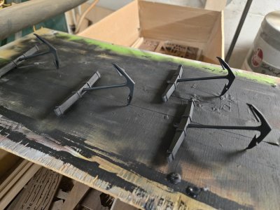
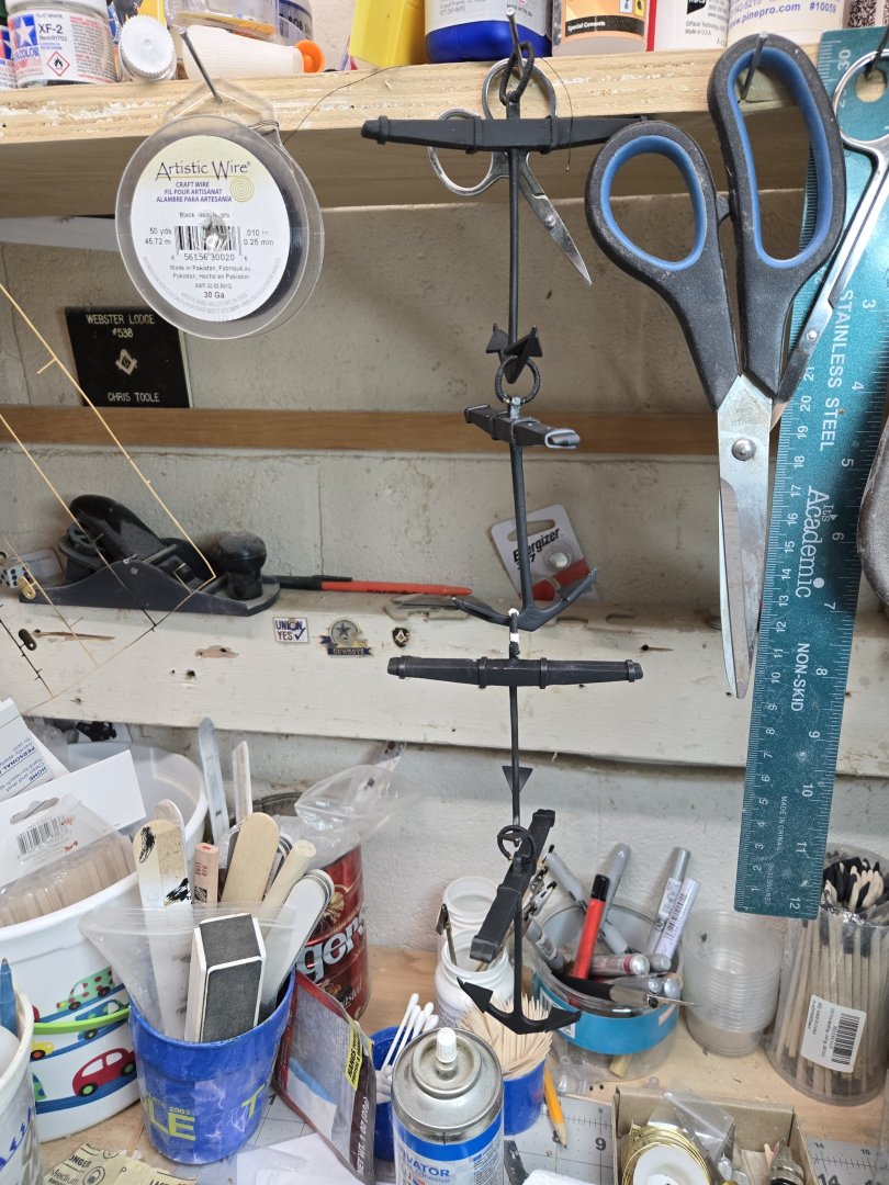
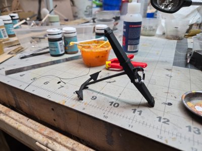
Fixing the anchor mistake didn't go well. I couldn't just push the anchors out of the stocks. I had glued them pretty good and there was no way to do that and the cast is so soft and that any real forcing will either break them or bend them.

So I cut them and reglued them. Hopefully the CA glue bond will be strong enough to hold up.

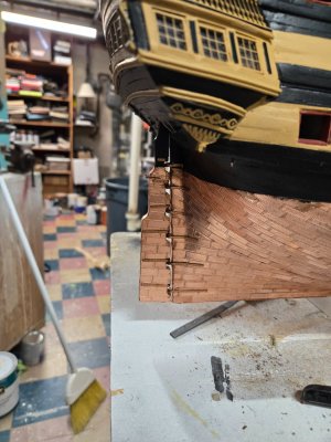
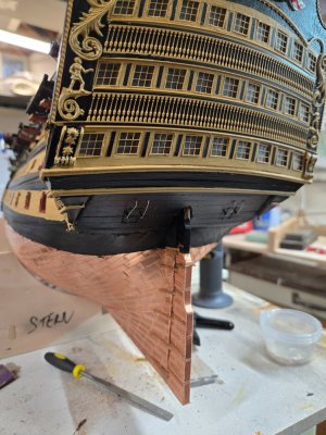
I also worked on the rudder. I have set the hinges in place but decided to cut off the little pins. I'll CA glue everything when it's set and hopefully it won't look too bad!

20241204_211540.jpg

20241204_211550.jpg
 
Worked on the anchors.

Which I have built incorrectly. I will need to go down and see (HOPE) if I can pull the cast anchor off the stock and turn them 90 degrees.

I have no idea what I was thinking...

I used 2mm styrene for the metal strapping on the stocks. I have seen one builder use wire shrink wrap. That would be a great idea. I have tons of different sizes, but they are all on my boat, laid up for the winter. I could have gone to Harbor Freight and buy a cheap set...but I had the styrene around.

The only problem is styrene breaks very easily around 90 degree bends. It required careful setting and some sanding and filling before painting.

You also have to sand and/or file the castings to smooth them out.

I used iron black to paint them. I like the subtle difference in the color compared to the dull black of the hull.

I will keep you posted on my adjustments!

View attachment 488276

View attachment 488277

View attachment 488278
Forget unmanagable styrene for the stock irons. Use blackened brass strip. It FOLDS well.
 
Forget unmanagable styrene for the stock irons. Use blackened brass strip. It FOLDS well.
Hi Chris,
I agree with Kurt that styrene is not a favorite. Softened brass was my go to until I found out how much easier it is to work and blacken copper strips. Nothing wrong with using poster board or similar card stock of the appropriate thickness. Even bond paper for 1:96 scale is a good way to go. As any of them are very dark to black they contrast well with the wooden stocks which were not painted.
Allan
 
Very nice Chris.
I love the netting reworked.
Your honesty in revealing your mistakes and how you approach correcting and redoing is refreshing.
I’m sure we all make mistakes, I certainly do, and by sharing with others hopefully we are not condemned to making the same ones.
Enjoying your log very much.
 
Hi Chris,
I agree with Kurt that styrene is not a favorite. Softened brass was my go to until I found out how much easier it is to work and blacken copper strips. Nothing wrong with using poster board or similar card stock of the appropriate thickness. Even bond paper for 1:96 scale is a good way to go. As any of them are very dark to black they contrast well with the wooden stocks which were not painted.
Allan
Are you guys talking about using left over PE sprue, or aftermarket thicker copper strips?
I'll have to remember this when I begin working on masts, but I think a lot of that banding is over rounded surfaces so might be less susceptible to breaking.

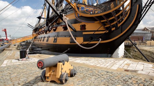
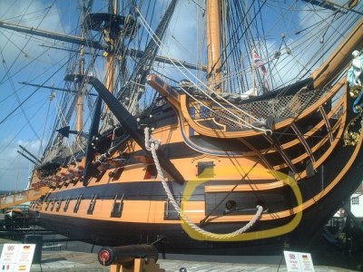
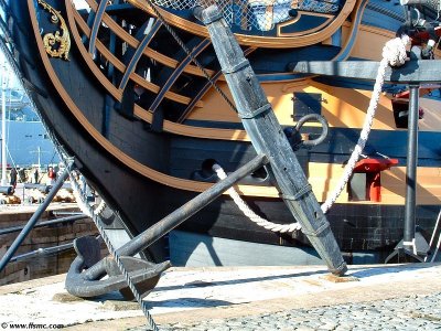
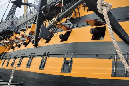
You say the stocks aren't painted, I thought about that but it seems that pictures of the live Victory show the stocks painted. Now that may be a case of expediency to keep them in good shape and protect them from the weather. Either way, too late as I've painted them!

126843-Portsmouth.jpg

46534710_7de1e540b9_z jjjj.jpg

Anchor at Dock.jpg

Broadside - Anchor Detail.jpg
 
Very nice Chris.
I love the netting reworked.
Your honesty in revealing your mistakes and how you approach correcting and redoing is refreshing.
I’m sure we all make mistakes, I certainly do, and by sharing with others hopefully we are not condemned to making the same ones.
Enjoying your log very much.
Thank you!
I enjoy doing it, it's a good debriefing for me when I finish things. To come upstairs, download whatever pics I took and give them a good look!

Appreciate the words.
Chris
 
ou say the stocks aren't painted, I thought about that but it seems that pictures of the live Victory show the stocks painted.
Sorry Chris, I overstated this. I have seen both unpainted and painted anchor stocks on contemporary models at RMG and Preble Hall. Painting them makes sense as it would protect the wood from the water but you may like the look of bare wood more. Your choice.
Allan
 
Are you guys talking about using left over PE sprue, or aftermarket thicker copper strips?
I'll have to remember this when I begin working on masts, but I think a lot of that banding is over rounded surfaces so might be less susceptible to breaking.

You say the stocks aren't painted, I thought about that but it seems that pictures of the live Victory show the stocks painted. Now that may be a case of expediency to keep them in good shape and protect them from the weather. Either way, too late as I've painted them!

View attachment 488328

View attachment 488329

View attachment 488330

View attachment 488331
These strips: Brass Strip 12" x 1/64" x 1/16"
 
Pugging on!

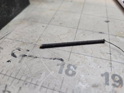
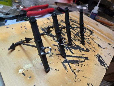
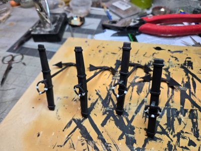
My idea of 'seizing' the brass wire before turning it into a ring actually worked...after some failures.
Tying one end, I was able to easily and quickly twist the tube while rolling the string around it. Every 5 or 6 turns I would put a dab of CA glue on it to keep the work I did set.

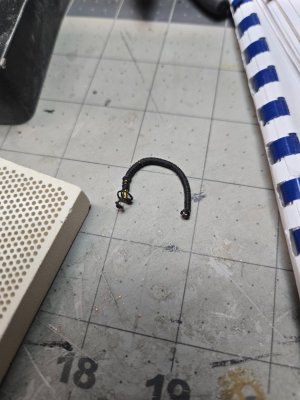
The problem was trying to bend it after! The instructions call for a 15.5mm diameter ring...which is about a 47.1mm circumference, or length of brass.
That is pretty short and VERY hard to bend. Even using some pliers, I ended up ruining the puddening on the ends.

Annealing the 4 pieces made them very easy to bend. I have a little mini butane torch and ceramic pad (you can see in one of the pics) and the process goes fast. I quenched the pieces and that did the trick. (you don't have to quench them, but it makes it easy to get back to work quickly)

Once done, I used a pair of round nose pliers (for making jewelry) and was able to bend them around a fat sharpy pen and then attach to anchor stocks. After the first one, I left about a 1mm bare on each end to facilitate their attachment. After that, I added a bit of black line to cover those bare spots.

Putting the tan decorative line on the 3 'corners' went fine. Although while doing this, it is apparent to me that adding the black line while the tubing was straight was far easier than what I would have encountered had I tried to add the black line to a ring...which would have required actually 'sewing' the line on.

A barrel of anchors....sorry, couldn't resist.
20241205_123856.thumb.jpg.ad5017e94e10daadbb276d88518d341a.jpg

For me though, the tan line was fairly dark as the CA glue does stain the line. I didn't like that, so I painted them white. Perhaps I could have added some black to dull down the white a bit, but in the end, it adds a nice contrast and I'm fine with it.

I also added the PE hinge straps to the rudder and hull. Once again, the directions just say to attach or secure the straps. There is nothing of detail there or on any of the many blue prints. However, the parts manual lists where each one goes and made it easy to make sure I did it correctly...given my propensity to not read ahead or follow simple instructions!

I also noticed that my waterline is a bit higher than it should be at the stern. Nothing I can do about that, but it seems that more of the rudder and the spectacle plate (the little PE piece that will hold the anchor chain for back up steering) should be black.

The rudder doesn't quite fit tightly to the hull at the bottom, but will pass casual observations. I did add a piece of copper plating to very bottom between the hull keel and the bottom of the rudder to help keep it in place in case it's bumped.

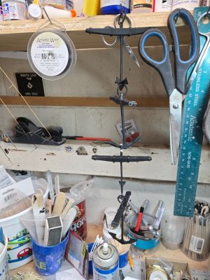
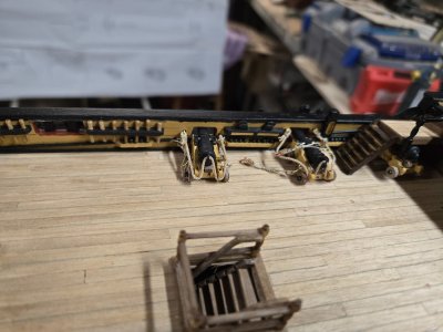
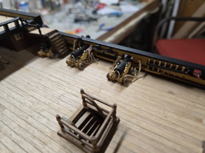
Also continued to work on the tackle rigging! Practice makes almost, close to getting there!
I have 4 down and 4 to go, then I still have to make and install the...'reset' tackle that pull the cannons away from the gun ports. So not even part way there. I also ran out of rounded pin nails, there is a hobby shop up the street that may sell these .6mmx10mm pins, we shall see!

20241205_112233.jpg

20241205_112550.jpg

20241205_123829.jpg

20241205_123856.jpg

20241205_123926.jpg

20241205_123938.jpg

20241205_145711.jpg

20241205_145742.jpg

20241205_161152.jpg

20241205_161201.jpg
 
Chris, your ship looks great and love your persistence in your build. You've come up with some great ideas on how to overcome some issues. I hope to get where you are in about a year or so. Keep up the good work. Bill
 
Good morning Chris. I’ve been away and had to do some catch up. Some fiddly bits been done. Cannon rigging and those nets. I recall doing those and I too had some redo’s. You owned this. I enjoy your “barrel” of anchors.

One thing about having a Victory model is she hogs the limelight. When guests come and visit all the comments and compliments are for my Victory while my Xebec (which is a better built model) only gets a cursory glance. :D .

Cheers Grant
Chris, your ship looks great and love your persistence in your build. You've come up with some great ideas on how to overcome some issues. I hope to get where you are in about a year or so. Keep up the good work. Bill

Once again, much appreciated Grant and Bill.

Been in Florida visiting, but I'm back home and ready to get back to work!
I have my three books....Longridge, McGowan and McKay open to the bowsprit. Honestly, their various takes, pics and instructions (especially Longridge) are FAR better than the instructions in the kit.

And yes...I'm still stalling on completing the cannon rigging.

I have started painting the hammock supports and will begin getting them in place and I just received my parts from Neil Wood's. I ordered his set of PE Victory letters and the depth numbers for the bow and stern. I think they are off a bit on the scale, but should fit nicely none the less.

As I said before, I must have cut the letters out of the sprue for some reason and set them aside somewhere. I'll find them in a few years, I'm sure.
I still have the 'old style' name plate, but can't figure out a way to neatly paint it. The lettering is raised, so I would want the base to be black and the tops yellow, but can't think of a way to make that happen.
 
Began working on the bowsprit, because I am still delaying the rigging of the last cannons and starting on the hammocks.

The instructions and the blueprints are a bit underwhelming when it comes to the building of the masts and yards. Perhaps if you've worked either on a Caldercraft model in the past or work on other square sailed ships, it will be more apparent. As my first, there is a lot of nomenclature that has to be learned.

Thankfully, there are some great builder logs here that I have been studying relentlessly!!!!

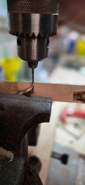
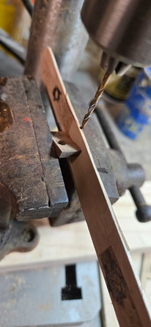
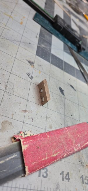
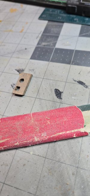
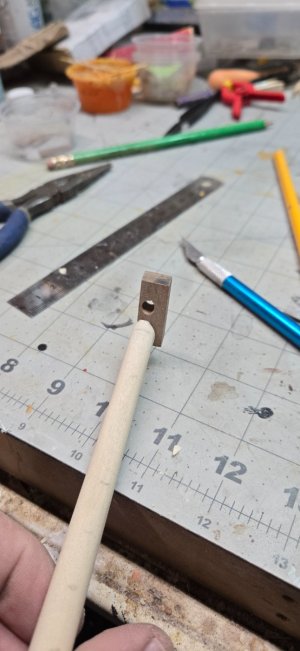
I started on the bowsprit. The first step is to create the cap (#69). You have to taper the ends and then add a square and round hole to fit both the end of the bowsprit (main mast so to speak) and the jib boom which runs through the cap out forward of the ship.

I tapered the ends using my disc/belt sander. Getting the exact points to drill the holes was a matter of lining up the cap with the diagrams (which are to scale). I was a bit too far to port when I finished, but shouldn't cause any issues. Drilling the hole at the same angle required the use of a bench vise, I aligned the drill bit parallel to the edge of the cap. I was able to drill the hole at the right angle and then use a rounded file to clean it up.

Doing the square hole was harder. I tried to drill 4 holes which I thought I would then cut out and file square. The problem I encountered was I used a small drill bit size and because of the angle of the wood I was drilling into, the bit tended to slide down the slope I had created.

I was able to drill 2 holes, but made this work.

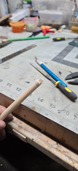
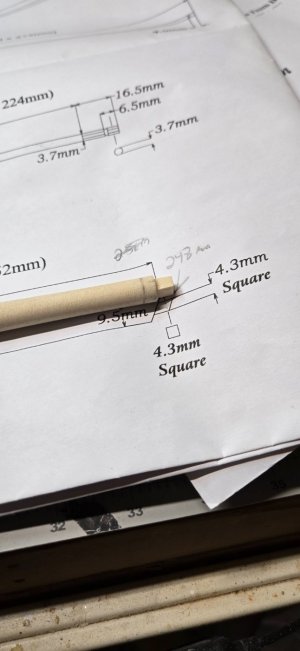
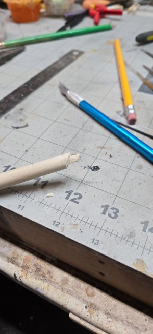
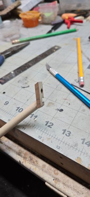
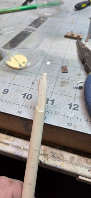
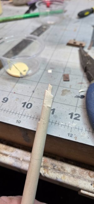
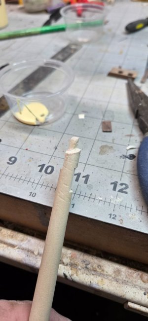
The next step was creating the square notch at the end of the bowsprit. Since this was my first attempt, I wasn't 100% sure what tactic to try.
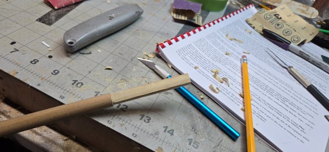
In the end, used a mini Japanese saw to cut small notches in the dowel. Then I used a sharp exacto knife to whittle down to a square. I also used a file to help square up my work. After creating the square peg, I tapered back the end to create an angle to fit into the cap.

As you can see, I am a bit too far over.

The next step was very confusing concerning the installation of the bees. Going through my books helped immensely. Again, I wish the instructions would include some better pictures of what they are talking about. The blueprints are fine, but they include all of the parts and they can become cluttered.

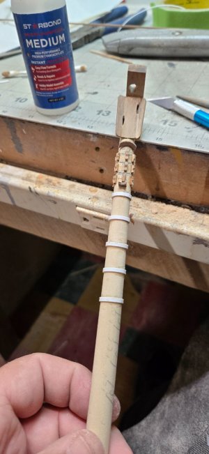
So you need to shave off material on the top of the bowsprit so that the flat bee (#415) fits flush on top. It as 2 notches, the starboard one is up front, the port one is about mid way. You have to then shave off material on both sides so that you can fit the bee sheaves (417, 418). These little pieces simulate a sheave which you could probably make real with aftermarket pieces. I didn't have sheaves that big, so I left them.

The starboard bee sheave fits tight to the cap. You would glue the cap, the flat bee on top and the 2 bee sheaves on each side.
Once attached, there are 2 pieces (416) simply called bees. These create little wings on top.

Glue all this together and if needed, apply some wood putty to smooth it all out. Be sure to clear the 2 holes for the sheaves, the books say the forestays will go through the holes.

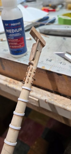
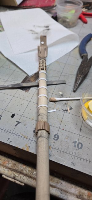
Once done with that, you have to add 3 rows of stop cleats. I believe each row has five 1.5x1.5mm walnut pieces about 2mm long. I cut them out and glued them as close to what the plan requires as I could. Once set, I used a round file to create the unique shape you see....just filing the bottom until they became rounded.

There are two other pieces that need to be installed and then I used 2mm styrene to create the bands.

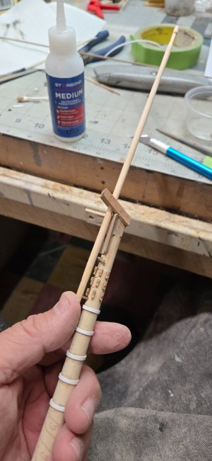
The next step was creating the gammoning stops lower on the bowsprit.

I cut little pieces of 1.5x1.5mm walnut and glued them onto the bowsprit. Using the plans I tried to get the angles correct. Honestly, I laid the bowsprit on the plans and tried to mark off where the stops should be. The pic in this post was my first attempt. I laid down white glue and then placed the walnut pieces on the dowel and tried to create the angle.

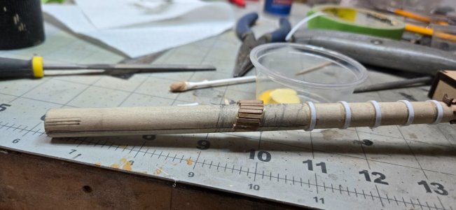
Creating the jib boom and flying jib boom required tapering and creating some 6 sided ends. I didn't do a very good job of this, they look like crap, but I think once they are painted, they'll clean up.

You also need 2 of the cast pieces to create the bracket to hold the flying jib boom to the jib boom. I was able to CA glue them and they seem to fit good. I tried to fit them together to see how it looks. I'll so some sanding and give the paint a shot at making it look good!

I then started on the fore mast. You have to create an 8mm square peg to one end with a smaller 6mm peg at the very end.
Doing the math, there would be 4.7mm of excess material that has to be cut away to create the 8mm center...or about 2.35mm on each end.

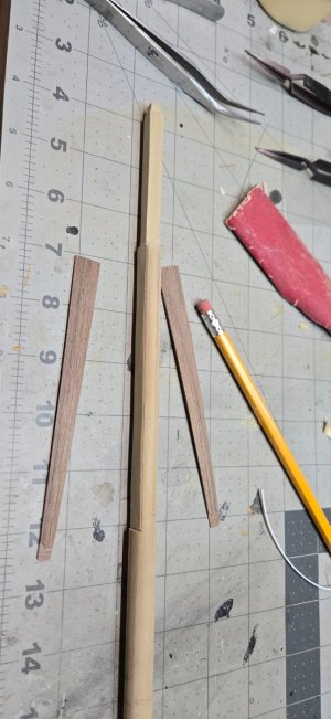
So I created the square on the end of the dowel and drew 4 lines to create a template to cut away. I then cut down about 1.5mm all around the dowel and using an exacto knife, I began cutting and/or shaving down. When I got close, I used a file to square things up. Cutting away was easy, but I did have to cut towards myself and I was very careful doing this, too many accidents when wood stops grabbing at the wrong time and the blade takes its own path....right into your hand.

When all was said and done, I think I got the squared off end pretty close to 8mm and then the little 6mm piece went pretty quickly.

After that, I had to create the flat sides for the cheeks (#343). I stopped after this, because the instructions require some banding under and over the cheeks. I wasn't sure if I needed to file space under the cheeks to fit the bands or allow then cheeks to have 'daylight' under them.

Also, there is another piece on the front of the mast, that isn't covered in this part of the instructions and there are a number of bands that once again, go above and below it. It's the rubbing paunch and is mentioned later on...can't wait!

So, tomorrow, I'll plod on!

20241215_141435.jpg

20241215_141443.jpg

20241215_142752.jpg

20241215_142900.jpg

20241215_144824.jpg

20241215_144830.jpg

20241215_150325.jpg

20241215_150339.jpg

20241215_150343.jpg

20241215_152112.jpg

20241215_152115.jpg

20241215_152118.jpg

20241215_234928.jpg

20241215_234938.jpg

20241215_235011.jpg

20241216_001801.jpg

20241216_001811.jpg

20241216_153501.jpg

20241216_162627.jpg
 
Began working on the bowsprit, because I am still delaying the rigging of the last cannons and starting on the hammocks.

The instructions and the blueprints are a bit underwhelming when it comes to the building of the masts and yards. Perhaps if you've worked either on a Caldercraft model in the past or work on other square sailed ships, it will be more apparent. As my first, there is a lot of nomenclature that has to be learned.

Thankfully, there are some great builder logs here that I have been studying relentlessly!!!!

I started on the bowsprit. The first step is to create the cap (#69). You have to taper the ends and then add a square and round hole to fit both the end of the bowsprit (main mast so to speak) and the jib boom which runs through the cap out forward of the ship.

I tapered the ends using my disc/belt sander. Getting the exact points to drill the holes was a matter of lining up the cap with the diagrams (which are to scale). I was a bit too far to port when I finished, but shouldn't cause any issues. Drilling the hole at the same angle required the use of a bench vise, I aligned the drill bit parallel to the edge of the cap. I was able to drill the hole at the right angle and then use a rounded file to clean it up.

Doing the square hole was harder. I tried to drill 4 holes which I thought I would then cut out and file square. The problem I encountered was I used a small drill bit size and because of the angle of the wood I was drilling into, the bit tended to slide down the slope I had created.

I was able to drill 2 holes, but made this work.

The next step was creating the square notch at the end of the bowsprit. Since this was my first attempt, I wasn't 100% sure what tactic to try.
In the end, used a mini Japanese saw to cut small notches in the dowel. Then I used a sharp exacto knife to whittle down to a square. I also used a file to help square up my work. After creating the square peg, I tapered back the end to create an angle to fit into the cap.

As you can see, I am a bit too far over.

The next step was very confusing concerning the installation of the bees. Going through my books helped immensely. Again, I wish the instructions would include some better pictures of what they are talking about. The blueprints are fine, but they include all of the parts and they can become cluttered.

So you need to shave off material on the top of the bowsprit so that the flat bee (#415) fits flush on top. It as 2 notches, the starboard one is up front, the port one is about mid way. You have to then shave off material on both sides so that you can fit the bee sheaves (417, 418). These little pieces simulate a sheave which you could probably make real with aftermarket pieces. I didn't have sheaves that big, so I left them.

The starboard bee sheave fits tight to the cap. You would glue the cap, the flat bee on top and the 2 bee sheaves on each side.
Once attached, there are 2 pieces (416) simply called bees. These create little wings on top.

Glue all this together and if needed, apply some wood putty to smooth it all out. Be sure to clear the 2 holes for the sheaves, the books say the forestays will go through the holes.

Once done with that, you have to add 3 rows of stop cleats. I believe each row has five 1.5x1.5mm walnut pieces about 2mm long. I cut them out and glued them as close to what the plan requires as I could. Once set, I used a round file to create the unique shape you see....just filing the bottom until they became rounded.

There are two other pieces that need to be installed and then I used 2mm styrene to create the bands.

The next step was creating the gammoning stops lower on the bowsprit.

I cut little pieces of 1.5x1.5mm walnut and glued them onto the bowsprit. Using the plans I tried to get the angles correct. Honestly, I laid the bowsprit on the plans and tried to mark off where the stops should be. The pic in this post was my first attempt. I laid down white glue and then placed the walnut pieces on the dowel and tried to create the angle.

Creating the jib boom and flying jib boom required tapering and creating some 6 sided ends. I didn't do a very good job of this, they look like crap, but I think once they are painted, they'll clean up.

You also need 2 of the cast pieces to create the bracket to hold the flying jib boom to the jib boom. I was able to CA glue them and they seem to fit good. I tried to fit them together to see how it looks. I'll so some sanding and give the paint a shot at making it look good!

I then started on the fore mast. You have to create an 8mm square peg to one end with a smaller 6mm peg at the very end.
Doing the math, there would be 4.7mm of excess material that has to be cut away to create the 8mm center...or about 2.35mm on each end.

So I created the square on the end of the dowel and drew 4 lines to create a template to cut away. I then cut down about 1.5mm all around the dowel and using an exacto knife, I began cutting and/or shaving down. When I got close, I used a file to square things up. Cutting away was easy, but I did have to cut towards myself and I was very careful doing this, too many accidents when wood stops grabbing at the wrong time and the blade takes its own path....right into your hand.

When all was said and done, I think I got the squared off end pretty close to 8mm and then the little 6mm piece went pretty quickly.

After that, I had to create the flat sides for the cheeks (#343). I stopped after this, because the instructions require some banding under and over the cheeks. I wasn't sure if I needed to file space under the cheeks to fit the bands or allow then cheeks to have 'daylight' under them.

Also, there is another piece on the front of the mast, that isn't covered in this part of the instructions and there are a number of bands that once again, go above and below it. It's the rubbing paunch and is mentioned later on...can't wait!

So, tomorrow, I'll plod on!

View attachment 490241

View attachment 490242

View attachment 490243

View attachment 490244

View attachment 490246

View attachment 490247

View attachment 490248

View attachment 490250

View attachment 490251

View attachment 490252

View attachment 490253

View attachment 490254

View attachment 490255

View attachment 490257

View attachment 490258

View attachment 490259

View attachment 490260

View attachment 490264

View attachment 490266
Well done Chris, this is indeed a challenging part
 
Back
Top