-

Win a Free Custom Engraved Brass Coin!!!
As a way to introduce our brass coins to the community, we will raffle off a free coin during the month of August. Follow link ABOVE for instructions for entering.
-

PRE-ORDER SHIPS IN SCALE TODAY!
The beloved Ships in Scale Magazine is back and charting a new course for 2026!
Discover new skills, new techniques, and new inspirations in every issue.
NOTE THAT OUR FIRST ISSUE WILL BE JAN/FEB 2026
You are using an out of date browser. It may not display this or other websites correctly.
You should upgrade or use an alternative browser.
You should upgrade or use an alternative browser.
HMS Vanguard 1787 1:72 a Victory Models kit
- Thread starter Chestcutter
- Start date
- Watchers 62
-
- Tags
- amati vanguard victory models
Ah yes. Much better in black!
better in black colour - 
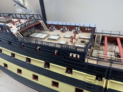
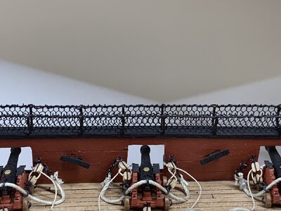
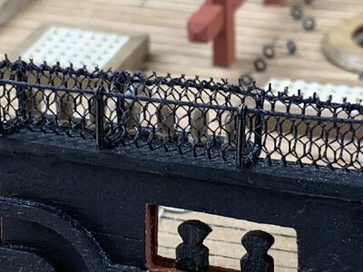
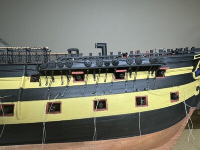
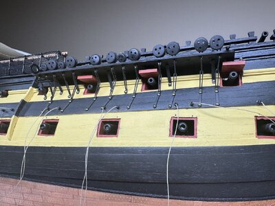
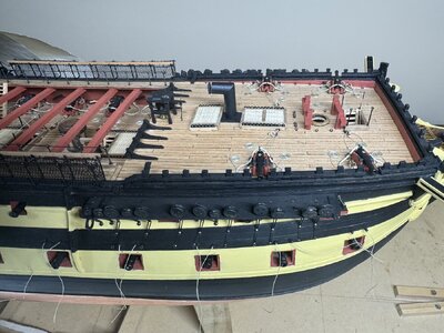
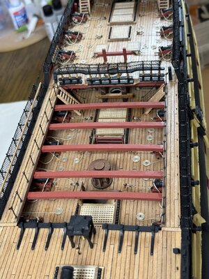
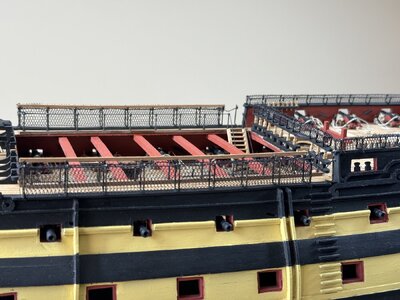
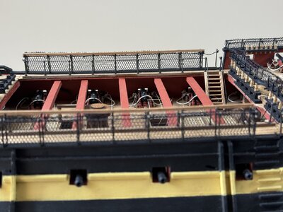
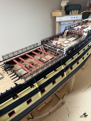
Finished doing all the hammock cranes in black.
For the future me and others who may be interested the best technique involved having parallel running rope thread through the tops of the cranes, reasonably taught.
Cut the netting with spare material above the intended fixation level, as the material can unravel, it is not tied.
Secure the netting with a running over and over thread along the rope thread, I used a quilting needle and cotton thread. At the ends leave a rectangular extension that can be hinged to close off the ends of the cranes.
Glue the knots to secure.
Here is the finished result. Much better than white.
Thanks for looking in.
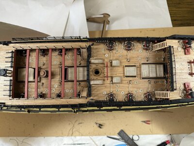


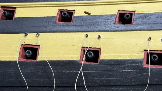
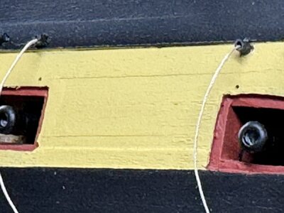
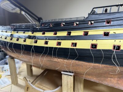
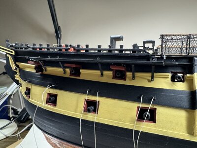
Next job is to prepare gunports lids for attachment. The 32 pounders on the gun deck are dummy barrels that need to be threaded into holes in a ply board strip. These holes should have been drilled before the gunports were lined and painted, which I didn’t do.
Drilling holes through the gunports was difficult and hazardous, but only a few minor grazes to the ports, which will need some minor repairs.
For each of the lower port lids there are four holes to drill, two for the hinges are 0.65mm spaced 10mm apart, for the belaying ropes two are 1.5mm spaced 9.5mm apart, 6mm above the hinge holes. Through these I have inserted electrical shrink tubing which has an outer diameter of 1.5mm when shrunk, to simulate the rope sleeves.
The 32 pounders and port lid holes are installed on the port side. Once the starboard side is done I will start work on the channels, and the upper gunport lids.


This is impressive work
Thank you for your kind comments Grant. I am inspired by seeing the work of others on this forum, yours included.This is impressive work
She's looking good so far. My only issue is that the gun ports should be sanded to present a "squared-away" appearance. But, my earlier models did not square everything. So, live and learn! And, most of all, enjoy the process.
Bill
Bill
Last edited:
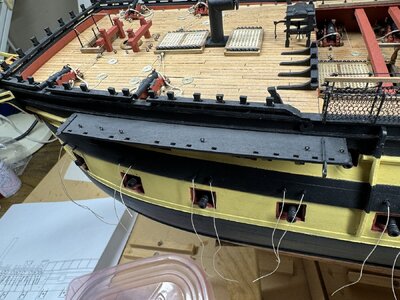
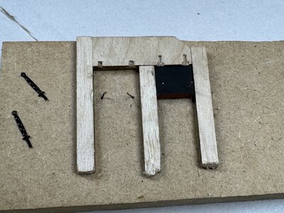
Have started on the channels. This is the port forward channel dry fitted. x4 1mm wires drilled to provide tensile resistance at contact with the hull, x5 brackets, x6 eyelets and the iron work for a spar. Also fitted the upper gunport lids for the ports that sit beneath the channel. Very tight fit. Used my dual gun port jig to fit the hinges.



Nice progress! This is all looking very good!
Very good template for the installation of the lid-hinges
Thank you for the encouragement PaulNice progress! This is all looking very good!
Thank you for the compliment.Very good template for the installation of the lid-hinges
The workflow and tempo of the build in this phase is very different to the hull and deck furniture construction. Still having fun.
Refining the sequence of steps in a component build is one of the improvements I have learnt in this build of my Vanguard.
The channels of which there are 8, four each side is a good example.
This is my refined sequence.
1: Glue the 2x1 walnut strips to the edges to close off the deadeye inserts. Rather than bending the wood I glued three pieces, filled the corner and sanded the round onto the corner. Then paint all black
2: Drill 1.1mm holes in the edge that meets the hull, to take the 1mm brass wire that provides anchoring and resists tensile lines
3: Of the 1:1 plans measure the leading edge of the support knees and the position of eyelets. Mark the underside with a pencil.
4: Drill holes for eyelets, 0.55mm
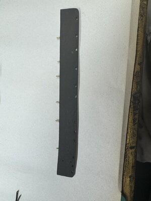
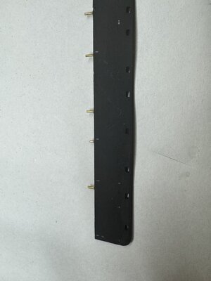
5: Pre bend the previously painted knees. Ream out the pinned hole to accommodate the custom nails (0.78mm)
6: Use CA to glue the knees and eyelets. Check orientation of the part to ensure the knees are flush with back edge and eyelets are 5mm from outer edge. Trim eyelets and turn down on underside to strengthen the tensile resistance. All eyelets are burnished copper.
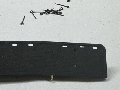
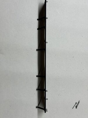
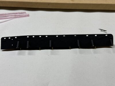
7: Dry fit the channel to check position of knees and the the pins all line up.
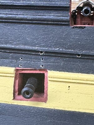
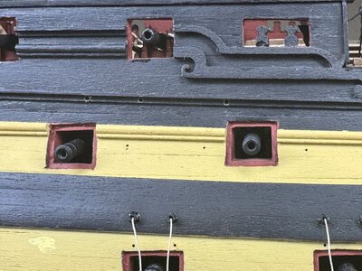
8: Many holes to be drilled for the channel and gunport lids which must be completed before channel is fitted, as access is lost to some lids.
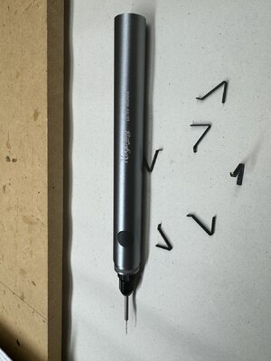
I bought a USB chargeable drill pen called a Nogarmy, and would suggest that a twist drill just can’t compete. This is an essential tool.
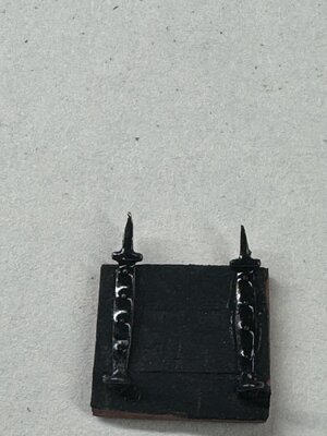
9: The upper gun port lids are smaller and I decided not to have an internal ring. After drilling the holes for hinges (0.67mm) and the ropes, I sanded the hinges to form a spike to facilitate entry into the wood. Then I added the ropes to the rings. Then fit the port lid with CA. After the lid was secured I fed the rope into the channel hole and CA sealed.
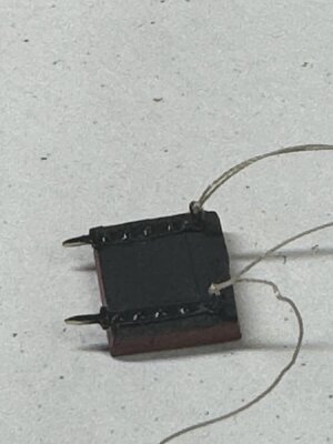
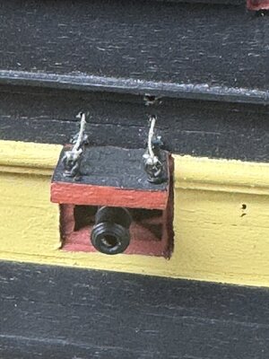
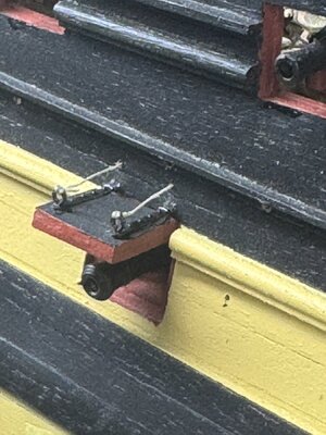
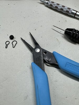
10: Refit the channel and mark out the point for the knee fixing point on the hull. Drill the hole (0.56mm) to facilitate the nail insertion, which was done with fine pliers, as it’s to hard to use a hammer or pin driver.
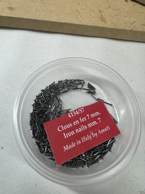
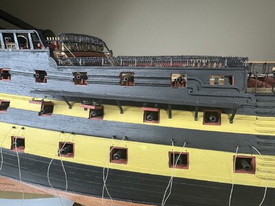
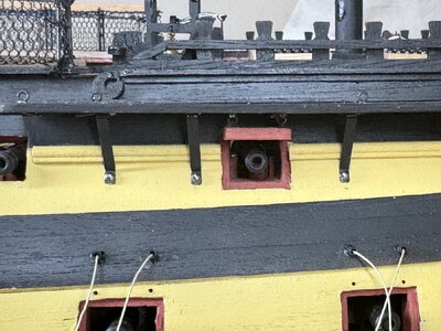

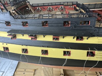
Thanks for checking in on my build.
Michael
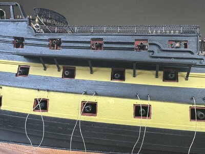
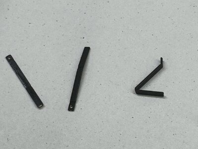
The channels of which there are 8, four each side is a good example.
This is my refined sequence.
1: Glue the 2x1 walnut strips to the edges to close off the deadeye inserts. Rather than bending the wood I glued three pieces, filled the corner and sanded the round onto the corner. Then paint all black
2: Drill 1.1mm holes in the edge that meets the hull, to take the 1mm brass wire that provides anchoring and resists tensile lines
3: Of the 1:1 plans measure the leading edge of the support knees and the position of eyelets. Mark the underside with a pencil.
4: Drill holes for eyelets, 0.55mm


5: Pre bend the previously painted knees. Ream out the pinned hole to accommodate the custom nails (0.78mm)
6: Use CA to glue the knees and eyelets. Check orientation of the part to ensure the knees are flush with back edge and eyelets are 5mm from outer edge. Trim eyelets and turn down on underside to strengthen the tensile resistance. All eyelets are burnished copper.


7: Dry fit the channel to check position of knees and the the pins all line up.
8: Many holes to be drilled for the channel and gunport lids which must be completed before channel is fitted, as access is lost to some lids.
I bought a USB chargeable drill pen called a Nogarmy, and would suggest that a twist drill just can’t compete. This is an essential tool.


9: The upper gun port lids are smaller and I decided not to have an internal ring. After drilling the holes for hinges (0.67mm) and the ropes, I sanded the hinges to form a spike to facilitate entry into the wood. Then I added the ropes to the rings. Then fit the port lid with CA. After the lid was secured I fed the rope into the channel hole and CA sealed.


10: Refit the channel and mark out the point for the knee fixing point on the hull. Drill the hole (0.56mm) to facilitate the nail insertion, which was done with fine pliers, as it’s to hard to use a hammer or pin driver.


Thanks for checking in on my build.
Michael


A nice work-flow that has achieved a fantastic result! Bravo!
Good afternoon. Awesome work. Reminds me of the victory with never ending sequence of gun port,Lids etc etc. Cheers GrantRefining the sequence of steps in a component build is one of the improvements I have learnt in this build of my Vanguard.
The channels of which there are 8, four each side is a good example.
This is my refined sequence.
1: Glue the 2x1 walnut strips to the edges to close off the deadeye inserts. Rather than bending the wood I glued three pieces, filled the corner and sanded the round onto the corner. Then paint all black
2: Drill 1.1mm holes in the edge that meets the hull, to take the 1mm brass wire that provides anchoring and resists tensile lines
3: Of the 1:1 plans measure the leading edge of the support knees and the position of eyelets. Mark the underside with a pencil.
4: Drill holes for eyelets, 0.55mm
View attachment 435725View attachment 435728
5: Pre bend the previously painted knees. Ream out the pinned hole to accommodate the custom nails (0.78mm)
6: Use CA to glue the knees and eyelets. Check orientation of the part to ensure the knees are flush with back edge and eyelets are 5mm from outer edge. Trim eyelets and turn down on underside to strengthen the tensile resistance. All eyelets are burnished copper.
View attachment 435729
View attachment 435730View attachment 435731
7: Dry fit the channel to check position of knees and the the pins all line up.
8: Many holes to be drilled for the channel and gunport lids which must be completed before channel is fitted, as access is lost to some lids.
I bought a USB chargeable drill pen called a Nogarmy, and would suggest that a twist drill just can’t compete. This is an essential tool.
View attachment 435727
View attachment 435734View attachment 435733
9: The upper gun port lids are smaller and I decided not to have an internal ring. After drilling the holes for hinges (0.67mm) and the ropes, I sanded the hinges to form a spike to facilitate entry into the wood. Then I added the ropes to the rings. Then fit the port lid with CA. After the lid was secured I fed the rope into the channel hole and CA sealed.
View attachment 435735View attachment 435736View attachment 435737View attachment 435738
10: Refit the channel and mark out the point for the knee fixing point on the hull. Drill the hole (0.56mm) to facilitate the nail insertion, which was done with fine pliers, as it’s to hard to use a hammer or pin driver.
View attachment 435739View attachment 435740
View attachment 435741View attachment 435742View attachment 435744
Thanks for checking in on my build.
Michael
View attachment 435732
View attachment 435726
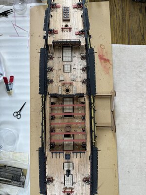
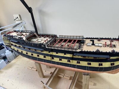
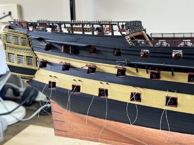
All channels fitted. Preparing the deadeyes, strops and chain plates. Fiddly painting them but I think the deadeyes are supposed to be black.
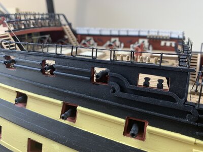
The keen eyed observer will notice the quarter deck canon doors are missing on the third from the stern port. The reason I left them off is because they would not fit with the decorative rail coming up to the port edge. If I were to do it again I would have stopped the rail short of the port opening and beveled the outward facing edge. I’m too scared to do this now for fear of causing damage.
Thanks for looking.


Nice clean work here Michael! Chains look GREAT!
Thanks Paul. Your words and your deeds are inspiring.Nice clean work here Michael! Chains look GREAT!


