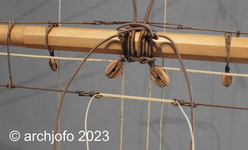
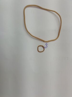
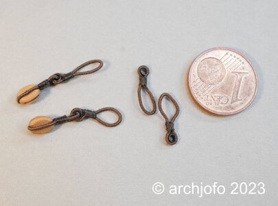
La Créole 1827 by archjofo - Scale 1/48 - French corvette

Always impressive your rigging work. About the block for the clew lines.

If it is a clew line block or garnet block depend on the type of block.

In your case it is a clew line block. Because you used in your case a standard block. Like a bunt line block, leech line block. (On Dutch ships they don't use a leech line block but a turtle block, what is integrated with the yard)

A garnet block, a better name is a clew garnet block, looks different but has the same function.
This is a clew garnet block
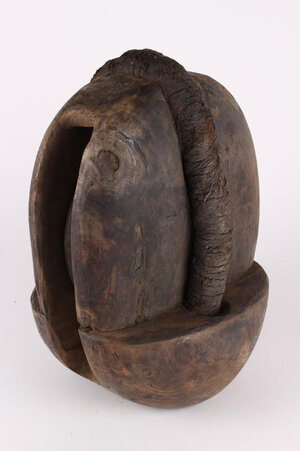
clew garnet block.jpg

The name garnet comes from the French word pomegranate, it looks like it.

You are sure to use on a French ship a standard block for this part of the rigging?
 
@Steef66
Hi Stephen,
thank you very much for your explanation. Then the designation of the blocks for the Clew lines of the La Creole is definitely "Clew line blocks". Then I was originally correct in my earlier report.
In the case of the La Créole, I am therefore certain that the clew line blocks were standard blocks.

K. H. Marquardt states in "Bemasting and rigging of ships of the 18th century" that the clew line blocks had a shoulder until 1775, which means that clew garnet blocks were used up to this point in time. After that time, Marquardt continues, standard single-disc blocks were used. Certainly there will have been a transitional period in which these clew garnet blocks gradually disappeared. Definitely no more clew garnet blocks should have been used from about 1800 onwards.

Also on contemporary models of the Paris Museum from the beginning of the 19th century, as well as on drawings in the Atlas du Génie Maritime, the Clew line blocks are always executed as normal standard blocks. It is also shown in the monograph on La Créole.
As far as I know, these shoulders, through which the strops went, should prevent the block from being pulled out of the strops when the sail flaps.
Actually a sensible arrangement.
It would be interesting to find out why they then switched to standard blocks.
 
It would be interesting to find out why they then switched to standard blocks.
Nice explanation about the blocks.
Why they change I think like many parts in rigging did. Evolution. For example shrouds. In old times a few shroud ropes where attached, the when the mast gets higher and higher, more shrouds where added. Then the backstays came and they discovered how more backstays, less shrouds where necessary. This happened also with the use of different materials. Chains take place of ropes. Better and stronger ropes, serving, etc. Makes changes too. So why use a special block when a standaard block also works and keep in that way the cost of production low. The most changes happen from 1600 - 1655
 
@Steef66
@Tobias
@Herman
Hi,
thank you very much, I'm glad you like it.

Continuation: Equipment of the lower yards - footropes and stirrups - Marchepieds et étriers
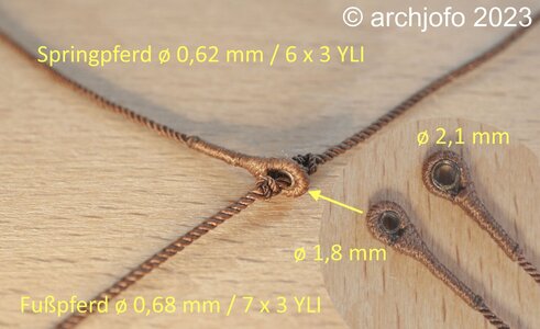
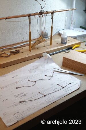
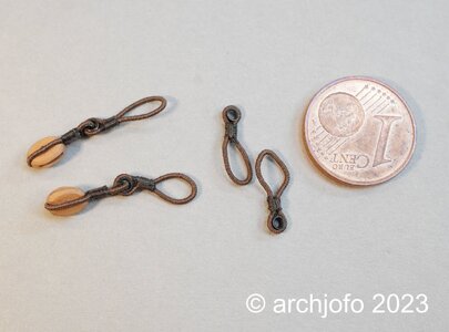
In the meantime the ordered brass tubes with various diameters arrived. In this respect, I found out that matching thimbles with ø1.8 mm for the jumpers can be made from brass tubes with ø1.1 mm.
DSC01170.jpg

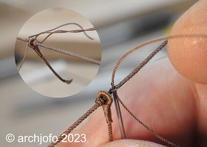
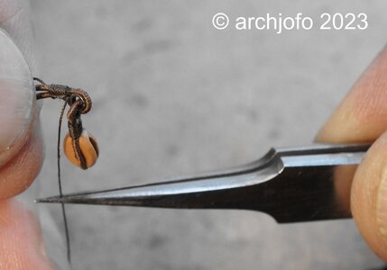
The stopper knots presented another challenge. To prevent the footropes from being pulled through the thimbles, for example, so-called "Turk's head knots" were woven in.
How are these knots to be depicted reasonably realistically in 1:48 scale?
Simple overhand knots do not look very good. After a number of attempts, I found a solution that looks reasonably acceptable in my eyes, as shown in the following picture.
DSC01178.jpg

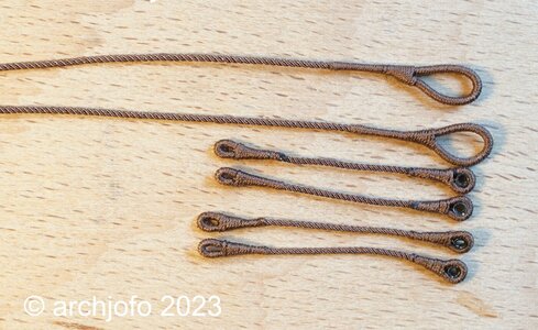
On the next picture the footropes and stirrups are ready for the next step.
DSC01176.jpg

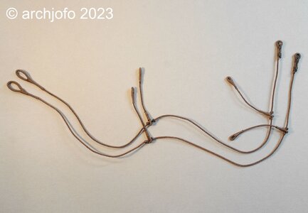
The stopper knots were now placed in the appropriate places as described before, and the stirrups were pulled in between. The original footrope was actually covered with leather between the stopper knots to prevent shame.
Four stirrups were sufficient for the lower beam lengths of a corvette.
DSC01180.jpg

Before I attach the footropes to the yard, I consider how to achieve the most realistic hang. From the top of the yard to the footrope a distance of about 1.05 - 1.10 m should be chosen. This way, the sailors could support themselves well with their feet and work hanging belly-down over the yard.
DSC01183.jpg

To be continued ...
 
Witaj
Jak zwykle wszystko pięknie zrobione i opisane, jestem pełen podziwu dla ciebie. Pozdrawiam Mirek
 
@Steef66
@Tobias
@Herman
Hi,
thank you very much, I'm glad you like it.

Continuation: Equipment of the lower yards - footropes and stirrups - Marchepieds et étriers
In the meantime the ordered brass tubes with various diameters arrived. In this respect, I found out that matching thimbles with ø1.8 mm for the jumpers can be made from brass tubes with ø1.1 mm.
View attachment 371452

The stopper knots presented another challenge. To prevent the footropes from being pulled through the thimbles, for example, so-called "Turk's head knots" were woven in.
How are these knots to be depicted reasonably realistically in 1:48 scale?
Simple overhand knots do not look very good. After a number of attempts, I found a solution that looks reasonably acceptable in my eyes, as shown in the following picture.
View attachment 371454

On the next picture the footropes and stirrups are ready for the next step.
View attachment 371453

The stopper knots were now placed in the appropriate places as described before, and the stirrups were pulled in between. The original footrope was actually covered with leather between the stopper knots to prevent shame.
Four stirrups were sufficient for the lower beam lengths of a corvette.
View attachment 371455

Before I attach the footropes to the yard, I consider how to achieve the most realistic hang. From the top of the yard to the footrope a distance of about 1.05 - 1.10 m should be chosen. This way, the sailors could support themselves well with their feet and work hanging belly-down over the yard.
View attachment 371456

To be continued ...
Every new detail of the rigging looks great, Johann.
Regards, Peter
 
@Steef66
@Tobias
@Herman
Hi,
thank you very much, I'm glad you like it.

Continuation: Equipment of the lower yards - footropes and stirrups - Marchepieds et étriers
In the meantime the ordered brass tubes with various diameters arrived. In this respect, I found out that matching thimbles with ø1.8 mm for the jumpers can be made from brass tubes with ø1.1 mm.
View attachment 371452

The stopper knots presented another challenge. To prevent the footropes from being pulled through the thimbles, for example, so-called "Turk's head knots" were woven in.
How are these knots to be depicted reasonably realistically in 1:48 scale?
Simple overhand knots do not look very good. After a number of attempts, I found a solution that looks reasonably acceptable in my eyes, as shown in the following picture.
View attachment 371454

On the next picture the footropes and stirrups are ready for the next step.
View attachment 371453

The stopper knots were now placed in the appropriate places as described before, and the stirrups were pulled in between. The original footrope was actually covered with leather between the stopper knots to prevent shame.
Four stirrups were sufficient for the lower beam lengths of a corvette.
View attachment 371455

Before I attach the footropes to the yard, I consider how to achieve the most realistic hang. From the top of the yard to the footrope a distance of about 1.05 - 1.10 m should be chosen. This way, the sailors could support themselves well with their feet and work hanging belly-down over the yard.
View attachment 371456

To be continued ...
Johann, your are doing wonderful work on the ropes, I'm learning from you allot methods Okay :)
 
@Mirek
@pianoforte
@Peter Voogt
@Fish&Chip
@shota70

Hello,
thank you very much for the nice comments.
Thanks also to everyone else for the LIKES.

Continued: Equipment of the lower yards - footropes and stirrups - Marchepieds et étriers
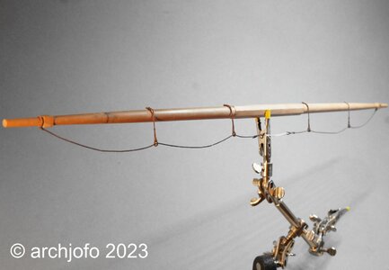
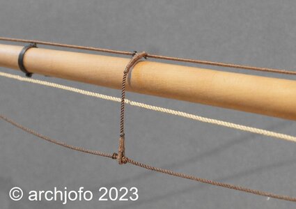
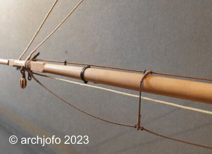
The arrangement of the footropes on the yards should be given as realistic an appearance as possible. In this respect, it is desirable to bring the stirrups vertically downwards and to let the drawn-through ropes of the footropes sag in their natural form.
In order to achieve this on a model scale, of course, a little help has to be given.
When making the yards, I initially made the main yard with incorrect yardarms. With this leftover yard I have already carried out tests on the arrangement for the jackstay. Now it serves me once more for experiments regarding the footropes. In this respect, I made provisional footropes and stirrups and installed them at the test yard.
After the ropes, which have been coated with diluted white glue, have dried and draped accordingly, the footropes look like the following picture:
DSC01186.jpg

In the right area of the yard it does not seem to be quite optimal and overall the sag is too big in my opinion, but I think that with this method I can achieve a good result for the model.
Soon...
 
@Uwek

Hello Uwe,

I don't usually do everything twice. But with the yards, it was simply due to the fact that I did the yardarms wrong. So, after extensive research, I made all the yards again, hopefully with the right yardarms.
But in this case it's very good, because I can try out a few things.
 
@Uwek

Hello Uwe,

Thank you for your positive comment.
I would like to thank the others for the LIKES.

Continued: Main yard equipment and others - Footropes and stirrups - Marchepieds et étriers - etc.
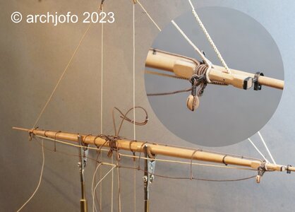
The blocks for the La Créole's braces were attached directly to the yard arms by strop. The connection of the blocks for the braces with the thimble sling was called "Dog and Bitch".
DSC01187.jpg

In addition to the strops for the braces, strops for the yard tackles also had to be considered, as can be seen in the following picture.
DSC01192.jpg

The yard tackles were then only attached when needed. In connection with the stay tackles, e.g. B. the boats are loaded and unloaded. The next picture shows the main yard with the newly installed rigging elements. For the lower yards, this corvette had simple yard lifts with a diameter of 30 mm, which went over blocks hooked into the tops for belaying on deck. The yard arms are now fully occupied. The footropes and stirrups that have already been attached still have to be properly lashed down in the middle of the frame.
DSC01210.jpg

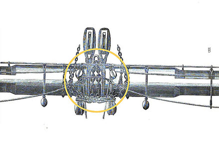
I still have to clarify in detail to what extent these lanyards can still be lashed over the sling of the lower yard, as shown in the following drawing by Nares. Unfortunately I don't have a meaningful picture of the original model.
Lower_Yard_Nares_1_wett.jpg
Source: Traité de manoeuvre et de matelotage, George S. Nares, 1868

The attachment of a stirrup to the jackstay can be seen in the next detailed pictures.
DSC01208.jpg

DSC01206.jpg


Finally a picture of the middle of the yard.
DSC01209.jpg

Except for the blocks for the clewlines and buntlines and the professional attachment of the stunsail booms, the main yard should then be fully equipped.
I would not have thought that so many rigging elements would have to be attached to a yard. I learned a lot from the research I did on the internet and relevant specialist literature. In the lower yards that follow, the production of the equipment should be all the faster. For the topsail, topgallant and royal yards, on the other hand, some detailed information is required that still needs to be obtained.
Sequel follows …
 
[USUARIO=6957]@Steef66[/USUARIO]
[USUARIO=12774]@Tobías[/USUARIO]
[USUARIO=15636]@Herman[/USUARIO]
Hola,
muchas gracias, me alegra que te guste.

Continuación: Equipamiento de los patios inferiores - reposapiés y estribos - Marchepieds et étriers
Mientras tanto, llegaron los tubos de latón pedidos con varios diámetros. En este sentido, descubrí que se pueden hacer dedales a juego con ø1,8 mm para los puentes a partir de tubos de latón con ø1,1 mm.
[ADJUNTAR=completo]371452[/ADJUNTAR]

Los nudos de tope presentaron otro desafío. Para evitar que las cuerdas para los pies se tiren a través de los dedales, por ejemplo, se tejieron los llamados "nudos de cabeza de turco".
¿Cómo se representan estos nudos de manera razonablemente realista en escala 1:48?
Los nudos simples simples no se ven muy bien. Después de varios intentos, encontré una solución que me parece razonablemente aceptable, como se muestra en la siguiente imagen.
[ADJUNTAR=completo]371454[/ADJUNTAR]

En la siguiente imagen, los reposapiés y los estribos están listos para el siguiente paso.
[ADJUNTAR=completo]371453[/ADJUNTAR]

Los nudos de tope ahora se colocan en los lugares apropiados como se describió anteriormente, y los estribos se colocan en el medio. El footrope original en realidad estaba cubierto con cuero entre los nudos de tope para evitar la vergüenza.
Cuatro estribos eran suficientes para las longitudes de viga inferior de una corbeta.
[ADJUNTAR=completo]371455[/ADJUNTAR]

Antes de colocar las cuerdas para los pies en el patio, considere cómo lograr la caída más realista. Desde la parte superior del patio hasta la cuerda inferior, se debe elegir una distancia de aproximadamente 1,05 - 1,10 m. De esta forma, los marineros podrían sostenerse bien con los pies y trabajar colgados boca abajo sobre la verga.
[ADJUNTAR=completo]371456[/ADJUNTAR]

Continuara.
 
Back
Top