Le Rochefort build log by OlivierF

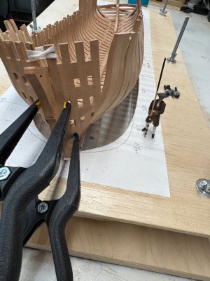
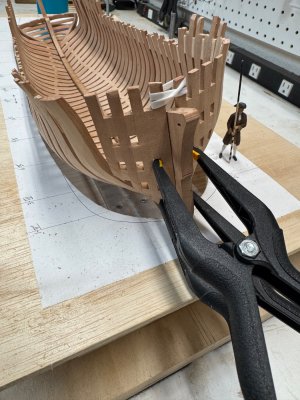
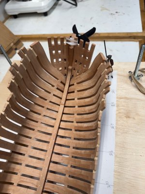
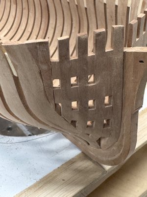
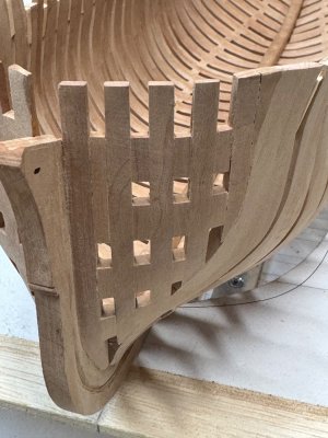
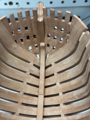
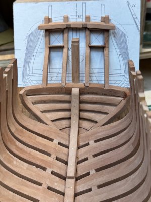
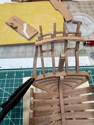
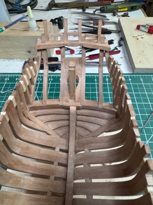
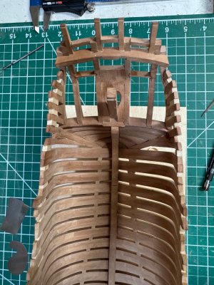
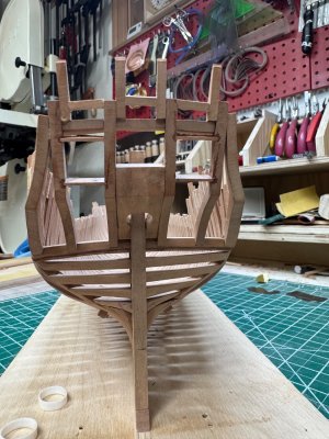
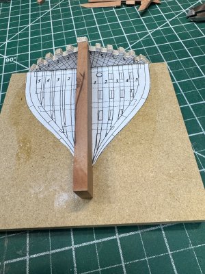
Well the bow assembly has been kicking my A$$… I have the individual hawse timbers correctly made since they’re exactly per the plans. It’s been the assembly that’s been a challenge. I finally started over and assembled a frame for the timbers.
IMG_8580.jpeg

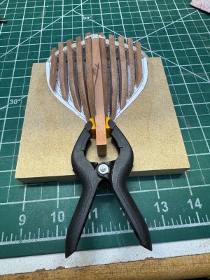
With this frame the Timbers seem to line up correctly.
IMG_8581.jpeg

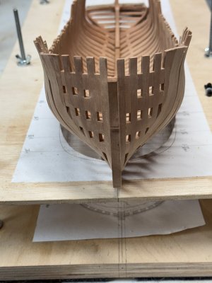
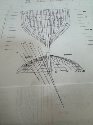
This is where I “discovered” the problem that I haven’t seen addressed anywhere. Or if it has been I missed it… anyway the filler pieces are NOT parallel. Adrien’s book simply says to make filler pieces 3.5 x 5 mm and size them according to the plans. Closer inspection of the plans and Visually looking at the Timbers in the construction frame confirms this.
IMG_8582.jpeg

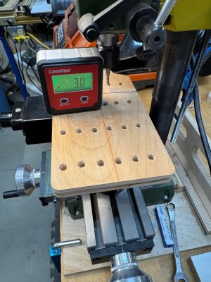
A little geometry of the angles confirms the filler pieces are angled and each are different.

Last step was to setup my mill to mill the filler pieces at the correct angles.
IMG_8583.jpeg

Now I’ll mill the filler pieces and hope it all works out.
More to come later. Now it’s break time. ;)Coffee
 
Hello Oliver, yes, the form is quite something. I checked my report again and I saw that I mentioned "filler pieces not at right angles" but it's very good that you mentioned it again. I will also put it in the information again. Your work looks very good.


Post in thread 'LE ROCHEFORT - Harbour yacht from 1787 1:36 by Tobias (Monograph by ANCRE)'
https://shipsofscale.com/sosforums/...y-tobias-monograph-by-ancre.10941/post-308772
Thank you Tobias. I did see your mention that the filler pieces were not at right angles but thought that to mean the pieces were not square to each other and did not realize your were meaning that they tapered fore and aft. Live and learn every day!
 
Thank you all for your Birthday greetings!
Since this I my day, I spent some time in the shipyard and got most of the hawse timbers installed.

IMG_8588.jpegIMG_8587.jpegIMG_8586.jpeg

I do, however, continue to struggle with the 5th timber. I’ve tried various methods to mill the correct angle to fit the first frame. I’ve tried milling at the appropriate angle using double stick tape, I’ve attempted cutting by hand with saw and chisel, I tried sanding both disk sander and by hand. It’s a good thing these are small pieces or I would have to buy up a forest of wood…

Anyway, I gave up for today so I think I’ll go have some birthday cake and open presents!

Thanks again everyone!

.
 
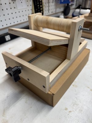
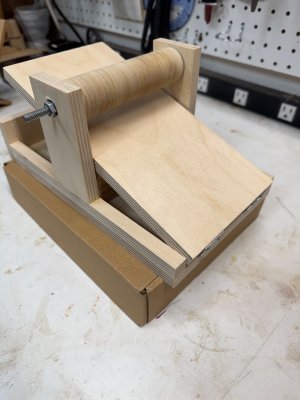
Before starting on the ship’s counter I decided to built a small drum sander as I’ve been struggling with getting planks the appropriate thickness overall.
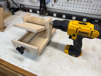
So, this is what I came up with using wood from the scrap bin and hardware I had laying around…

IMG_8605.jpegIMG_8607.jpeg
The drum is 5” long and 1.5” in diameter. The table is 5” wide and 10” long. I think this should be fine for the small scale of the timbers used in modeling.
I don’t have any of the right kind of sandpaper so I’ve ordered a 2” roll of 120 grit PVA backed sand paper.
I’ll have to wait for a test drive until the paper arrives.

I think I may also install a dedicated motor and not use a drill… we’ll see…

IMG_8609.jpeg
 
Last edited:
Nice, I was thinking about making one too. How did you get the shaft perfectly centered ? Actually I want to make better drums for my drill press out of wood. How are you fastening the paper to it ? A slot ?
 
Thanks Tony. For centering the shaft I carefully measured everything about 10 times. ;) Before assembly and glueing.
The sandpaper I ordered has adhesive backing and will be rolled on at an angle just like on the big drum sanders. I’ll send a picture of that once the paper arrives.
Ah ok yes. I have the rubber type of drums for the drill press. They’re not accurate or perfectly square.
 
Ah ok yes. I have the rubber type of drums for the drill press. They’re not accurate or perfectly square.
I understand your frustration as I have the rubber type on my oscillating spindle sander. I modified that and made a “luthier”s friend” type of setup. It works ok but I think the rubber deflects or something which causes inconsistency. Anyway, I’ll let you know how the hard wooden drum works out…
 
I understand your frustration as I have the rubber type on my oscillating spindle sander. I modified that and made a “luthier”s friend” type of setup. It works ok but I think the rubber deflects or something which causes inconsistency. Anyway, I’ll let you know how the hard wooden drum works out…
I have the luthiers friend. It works for strips but I had to make a fence to keep the strip straight so there are no valleys. Not perfect but does the job. The drum on it is better than the generic sanding drums I have. I wish there were affordable small surface planers.
 
Last edited:
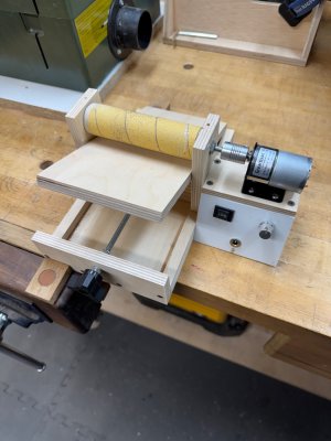
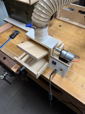
I’m calling my little drum sander a SUCCESS!!!
I did go ahead and install a dedicated motor. I also used a speed control and reverse switch which is probably overkill in hindsight.
Finally I 3D printed a dust hood which works perfectly.

IMG_8610.jpeg
IMG_8611.jpeg


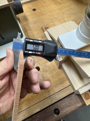
This little test plank came out at exactly 5.0mm!
IMG_8613.jpeg

I’m happy and can now continue to close the stern.
 
I’ve been working on the counter timbers and its assembly. The 4 main Timbers are pretty straight forward to construct. However, figuring out all the curves and angles for the horizontal quarterdeck timber and the taffrail Timbers took some time and a few trials before getting acceptable results.

IMG_8617.jpeg
IMG_8618.jpeg

Then it was on to the side counter timbers which also have multiple angles and curves.
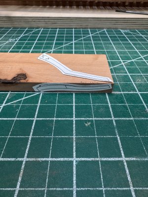
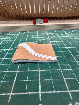
I used a modified version of how @Tobias made his pieces. Like Adrian’s book shows I used a narrower starting piece of 9mm (Tobias started with a 20mm blank) and cut the profile on the bandsaw and finished sanding on the spindle sander. Once the profile was done I glued the side piece and then cut them out. This worked quite well and now it’s just a matter of shaping the “foot” to the wing transom.
IMG_8621.jpeg
IMG_8624.jpeg
IMG_8623.jpeg
IMG_8622.jpeg

Next will be the partial frames on the sides and the stern will closed in…
 
The stern is now closed in and the counter is complete except final sanding and scraping to smooth everything out.

IMG_8628.jpegIMG_8629.jpegIMG_8630.jpeg


Next step was to mill the wood for the deck clamp. In reviewing the scantling table it appears that there is an error in the width of the deck clamp as the table calculates to 4.5mm but the drawings scale to 2.5mm and Adrian made his deck clamps as 2.4mm. Anyway, 4.5mm is simply to thick so I made them 2.5mm.
IMG_8631.jpeg

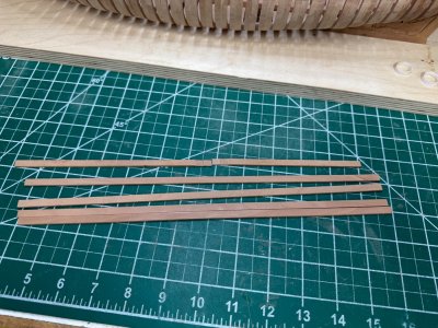
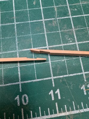
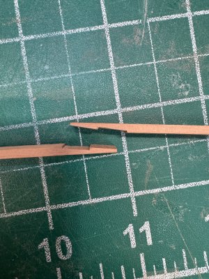
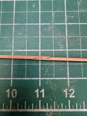
I then made one of the scarf joints in keeping with the drawings and Adrian’s book.
IMG_8625.jpeg
IMG_8626.jpeg
IMG_8627.jpeg

I’m simply not sure if making the scarf joints is worth it… will they even be visible once the deck beams and waterways are installed? I need to think about that as making the scarf joint took me about 1.5 hours to make the one!!!

Any thoughts from @Tobias or @Titoneri or others?
Thanks for any insight…
 
Back
Top