YUANQING BLUENOSE - Peter Voogt [COMPLETED BUILD]

Thanxs for your concern and thinking with me, Dean. Post 1000 in this build-log is to attention to you!
The orientation of the masts is still a bit flexibel. When I have completed all the deck beam and start with the deck, I fit the masts with the sqared fillings. Then I glued the lower parts. The first riggings are cruciaal for the correct position. Still quite a challenge!
Regards, Peter
I see...good plan sir! ;) Let the upper mast, once rigged, determine the orientation of the lower mast! Thumbsup
 
I see...good plan sir! ;) Let the upper mast, once rigged, determine the orientation of the lower mast! Thumbsup
Yep, the pin in the lower part fits with a very little friction in the hole in the bottom of the upper part. Just enough to angle with each others and to be put together and taken apart.
And I chose the zig-zag to prevent twisting of rotation. By building up the masts I have to keep the orientation in mind. But I think I can manage that. ;) Otherwise, I am sure you or some one else will ring the Ships Bell! :)
Regards, Peter
I think your idea of splicing the masts is beautiful, also the execution with the zigzag is ingenious. Okay
 
Thanxs for your concern and thinking with me, Dean. Post 1000 in this build-log is to attention to you!
The orientation of the masts is still a bit flexibel. When I have completed all the deck beam and start with the deck, I fit the masts with the sqared fillings. Then I glued the lower parts. The first riggings are cruciaal for the correct position. Still quite a challenge!
Regards, Peter
Do I win anything for being in post 1,000? :p
Seriously, I look forward to your updates! I am really enjoying following you on this build. ;)
 
Thanxs, Johan, Henk and Uwek, for appreciating my solution.
Regards, Peter
Hey Peter,

Just bugging me since I saw your solution to splicing the masts; do you have any means of "guiding" the upper masts to the mast parts in the lower shell? Probably missed it, but I would guess you'd have like a tapered pin/hole or something to guide the upper mast to its proper location in relation to the lower mast parts... Or do you rely on the zigzagging to take care of that?

Kind regards, Johan
 
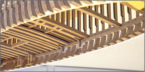
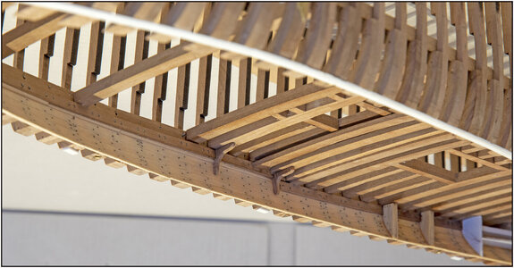
In post #911 I already showed that there are 3 pairs of Hanging Knees. The 2 remaining ones are under the deck beams I just fitted: under the first double beam of the raised aft deck and under thicker composite beam behind the main mast.
After the necessary filing and sanding, these were also made to fit:
To starboard:
439 Knie.jpg
To port:
440 Knie.jpg
I now have very soft and smooth fingertips on my thumb and index finger.Okay
And I've been on my knees on the floor several times when another one jumped out of my fingers. :)
Regards, Peter
 
Last edited:
In post #911 I already showed that there are 3 pairs of Hanging Knees. The 2 remaining ones are under the deck beams I just fitted: under the first double beam of the raised aft deck and under thicker composite beam behind the main mast.
After the necessary filing and sanding, these were also made to fit:
To starboard:
View attachment 268860
To port:
View attachment 268861
I now have very soft and smooth fingertips on my thumb and index finger.
And I've been on my knees on the floor several times when another one jumped out of my fingers. :)Okay
Regards, Peter
Herausragend!
 
Hey Peter,

Just bugging me since I saw your solution to splicing the masts; do you have any means of "guiding" the upper masts to the mast parts in the lower shell? Probably missed it, but I would guess you'd have like a tapered pin/hole or something to guide the upper mast to its proper location in relation to the lower mast parts... Or do you rely on the zigzagging to take care of that?

Kind regards, Johan
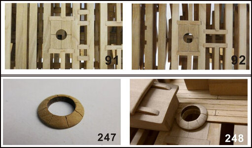
Block pieces will be added to the square openings in the deck beam. They are shown in the manual in photos 91 and 92.
And there is also a collar on it, photos 247 and 248.
91-92-247-248.jpg
I won't make that until I've finished the hull and working on the deck. Then I can fix everything and align. The 2 mast parts fit together with the pin-and-hole connection.
The ‘standing rigging’ will hold the masts in position.
Hopefully I answered your question with this?
regards, Peter
 
Last edited:
In post #911 I already showed that there are 3 pairs of Hanging Knees. The 2 remaining ones are under the deck beams I just fitted: under the first double beam of the raised aft deck and under thicker composite beam behind the main mast.
After the necessary filing and sanding, these were also made to fit:
To starboard:
View attachment 268860
To port:
View attachment 268861
I now have very soft and smooth fingertips on my thumb and index finger.Okay
And I've been on my knees on the floor several times when another one jumped out of my fingers. :)
Regards, Peter
Looks great Peter!
I have crawled on the floor looking for parts in the carpet many times... and have given up on occasion and made new ones! ;)
 
Last edited:
Block pieces will be added to the square openings in the deck beam. They are shown in the manual in photos 91 and 92.
And there is also a collar on it, photos 247 and 248.
View attachment 268862
I won't make that until I've finished the hull and working on the deck. Then I can fix everything and align. The 2 mast parts fit together with the pin-and-hole connection.
The ‘standing rigging’ will hold the masts in position.
Hopefully I answered your question with this?
regards, Peter
Not entirely there yet and I hope I'm seeing "lions and bears on the road", but I experienced (and admittedly, the holes for the masts were slightly oversized on my Bluenose model) that the standing- ánd running rigging did influence the orientation of the masts. So if you consider the deck feedthroughs as hinge points for the upper mast parts, one could affect the alignment of the interface with the lower mast parts by tightening or loosening any of the rigging ropes.
As long as you don't separate the two halves, there's no issue, but alternating between connected and separated in combination with the influence of varying temperatures, fluctuating humidity and the elasticity/flexibility of the rigging and the model's structure you could experience misalignment. How much? I really wouldn't know.
That's why I assumed a tapered pin/bush interface.
Still, highly impressed with your ideas and your planning way ahead of the build; Thumbsup

Kind regards, Johan
Regarding your concerns, if the mast hole is tight (controlled by square plate with hole, planking around it and mast base), then the shroud lines and stays, along with gluing the upper mast, will keep the upper mast very rigid. At which point, he can then align the notch in the lower masts with the now permanently fixed upper masts, and glue the lower masts in place. In addition I believe he said the pin in the lower mast is tapered. I would recommend a tapered lead in or chamfer in the hole ( made with a rat tail file) in the upper mast as well, to ensure alignment… if he hasn’t already done that. ;)
 
Last edited:
Regarding your concerns, if the mast hole is tight (controlled by square plate with hole, planking around it and mast base), then the shroud lines and stays, along with gluing the upper mast, will keep the upper mast very rigid. At which point, he can then align the notch in the lower masts with the now permanently fixed upper masts, and glue the lower masts in place. In addition I believe he said the pin in the lower mast is tapered. I would recommend a tapered lead in or chamfer in the hole ( made with a rat tail file) in the upper mast as well, to ensure alignment… if he hasn’t already done that. ;)
Yes, I'm there, I see the pin/hole in the mast parts. And your recommendation of tapering the hole makes a lot of sense. Let's wait and see what concoctions Peter is brewing. Fascinating build.
 
Not only is this visually an extraordinary build, but also from a technical point of view. I also think that securing the upper mast first and then aligning the bottom one in accordance to that, would be the way to go. However, I am positive that Peter has that all well covered.
 
Not entirely there yet and I hope I'm seeing "lions and bears on the road", but I experienced (and admittedly, the holes for the masts were slightly oversized on my Bluenose model) that the standing- ánd running rigging did influence the orientation of the masts. So if you consider the deck feedthroughs as hinge points for the upper mast parts, one could affect the alignment of the interface with the lower mast parts by tightening or loosening any of the rigging ropes.
As long as you don't separate the two halves, there's no issue, but alternating between connected and separated in combination with the influence of varying temperatures, fluctuating humidity and the elasticity/flexibility of the rigging and the model's structure you could experience misalignment. How much? I really wouldn't know.
That's why I assumed a tapered pin/bush interface.
Still, highly impressed with your ideas and your planning way ahead of the build; Thumbsup

Kind regards, Johan
Regarding your concerns, if the mast hole is tight (controlled by square plate with hole, planking around it and mast base), then the shroud lines and stays, along with gluing the upper mast, will keep the upper mast very rigid. At which point, he can then align the notch in the lower masts with the now permanently fixed upper masts, and glue the lower masts in place. In addition I believe he said the pin in the lower mast is tapered. I would recommend a tapered lead in or chamfer in the hole ( made with a rat tail file) in the upper mast as well, to ensure alignment… if he hasn’t already done that. ;)
Yes, I'm there, I see the pin/hole in the mast parts. And your recommendation of tapering the hole makes a lot of sense. Let's wait and see what concoctions Peter is brewing. Fascinating build.
Not only is this visually an extraordinary build, but also from a technical point of view. I also think that securing the upper mast first and then aligning the bottom one in accordance to that, would be the way to go. However, I am positive that Peter has that all well covered.
First of all, I want to emphasize that I really appreciate your contributions! And that you think along with the mounting of the masts, which is quite a fragile subject! :)
Let me try to reassure you. I don't see any bears of lions on the road and I thought about it for quite a while.
The fixation in the deck:
The blocks that should be placed in the recesses between the deck beams now have a throughput that is too small for the masts:
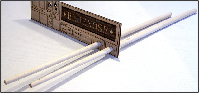
441 Mast.jpg
I can sand them to size and little angle so that the transit point of the masts is exactly in line and that they clamp. And I can aligning both mast parts through that hole to glue at the same time the bottom part in the mast feet and the upper part in block hole.

The connection of the mast parts:
The pin does indeed have a little chamfer at the top:
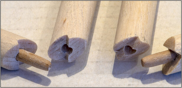
442 Mast.jpg
This is very macro of the 8.5 mm / 0,333" masts with the 3.0 mm pins (as opposed to the previously mentioned 2 mm).
In my opinion sufficient to find the centering to slide into each other even with the slight slant to the rear of the masts.
PS: Only the masts were cut diagonally and then filed into shape with the jeweler's files.

The friction of the connection:
The pins in the bottom part has such a thickness that they clamps slightly. Free hanging, with the immense weight of a clothespin ;), it does not slide out:
443 Mast.jpg
Just enough to slide when I put both hull parts together or take them out.

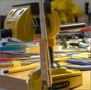
The fit of the pin and hole:
I can clamp the lower part in the vice and then the mast only bends a little bit:
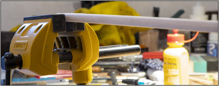
444 Mast.jpg

Once the masts are in place, the shrouds, and (side) stays will fix the masts imposition. I am confident that will last for many years to come. My Mirage has been standing for almost 40 years now. And when I take her out of the display case to clean it on the inside, I can still grab her by the masts and lift her up.

So, I hope you can relax and sit back. :)
Regards, Peter
 
Last edited:
Phew, you sure have given this design detail a lot of thought...Okay
Relax- and sitting back modus switched back on and again enjoying the show!

My concerns were driven by my experiences during my professional career where I dealt almost on a daily basis with interfaces. The transition to 3D design, CNC machining and CMM measurement improved accuracy immensely, but Murphy was always just around the corner.
You have achieved very precise and complex woodwork in the joinery of your mast junctions. Well done! Rich
 
Back
Top