Thank you for this information Michele, I see this is a much better way to make this part...Ciao, se può esserti utile, qui sotto puoi vedere le immagini di come ho realizzato la polena da un unico blocchetto di bosso.View attachment 281800View attachment 281801View attachment 281802View attachment 281803View attachment 281804View attachment 281805View attachment 281806View attachment 281807View attachment 281808View attachment 281809View attachment 281810View attachment 281811View attachment 281812View attachment 281813View attachment 281814View attachment 281815View attachment 281816View attachment 281817View attachment 281818
Questa è la polena dell'Orient rappresentata come alternativa nella monografia dei 118 cannoni Le Commerce de Marseille di Gerard Delacroix.
Nella monografia Gerard Delacroix propone la polena dei 120 cannoni Dauphin Royal del 1791 prima che nel 1795 gli è cambiato il nome in Oriente.
La feci una prima volta anni addietro quando ancora non avevo fatto la serpe e l'ho dovuto rifare in quanto c'erano delle cose che dovevano essere corrette.
Dalle foto potete vedere che le gambe risultavano troppo sottili una volta praticata la fessura creata per incorporarla nello sperone e la parte finale sarebbe quasi scomparsa.
Inoltre ho pratico lo scasso meno profondo, ho mantenuto un paio di millimetri in più per non trovarmi a forare il busto in fase di rifinitura. Così pure ho dovuto rivedere l'apertura alare che non è abbastanza sufficiente per accogliere la polena. Ho provato anche a rosicchiare qualche millimetro ma non mi piaceva affatto. Quindi ho dovuto rifarla, pazienza, anche se devo ammettere che quella precedente aveva alcuni errori dovuti alla mia inesperienza d'allora. Circa 80 ore di lavoro...
Nella prima foto puoi vedere le modifiche a cui mi riferivo e la vecchia polena poi rifatta.
Nelle altre tre la polena originale del Dauphin Royal.
-

Win a Free Custom Engraved Brass Coin!!!
As a way to introduce our brass coins to the community, we will raffle off a free coin during the month of August. Follow link ABOVE for instructions for entering.
-

PRE-ORDER SHIPS IN SCALE TODAY!
The beloved Ships in Scale Magazine is back and charting a new course for 2026!
Discover new skills, new techniques, and new inspirations in every issue.
NOTE THAT OUR FIRST ISSUE WILL BE JAN/FEB 2026
You are using an out of date browser. It may not display this or other websites correctly.
You should upgrade or use an alternative browser.
You should upgrade or use an alternative browser.
Le Commerce de Marseille 1788 - 1801 scale 1:48 from Gerard Delacroix
Amidships three there are three frames that are exactly identical. I thought, I'm going to make all three at the same time instead of one by one.... Not that I have the impression that this went so much faster or easier, it was a satisfaction to cross off three frames instead of one 
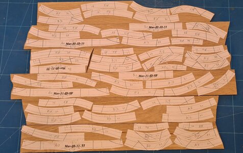
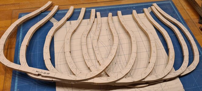
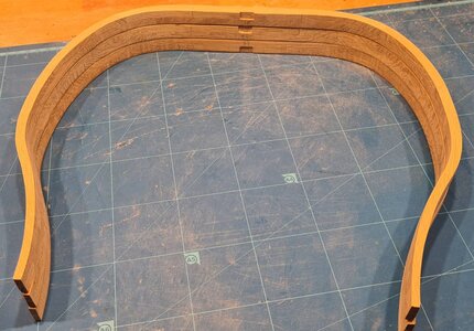
On the next photo you can see that the frames are turned amidships. Frame 33 is mirrored compared to frame 32...
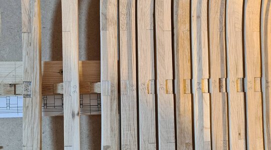
And a few pictures of the current status...
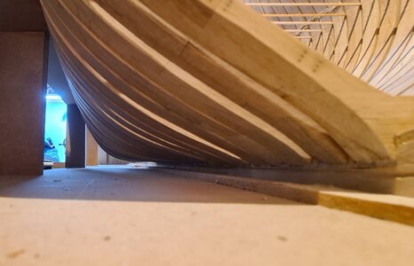
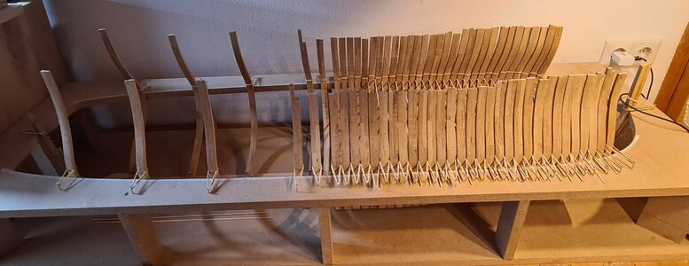
With these three at the same time, I'm already well past halfway. Of the 65 frames, 35 are now ready...
I'm thinking about doing two more frames, and then starting to mount the frames from amidships towards the bow on the keel after which I'm going to make the bow. The only reason is: some variety of work...
To the best of your knowledge, are there any reasons to or not to do this? Or doesn't it really matter?


On the next photo you can see that the frames are turned amidships. Frame 33 is mirrored compared to frame 32...

And a few pictures of the current status...


With these three at the same time, I'm already well past halfway. Of the 65 frames, 35 are now ready...
I'm thinking about doing two more frames, and then starting to mount the frames from amidships towards the bow on the keel after which I'm going to make the bow. The only reason is: some variety of work...
To the best of your knowledge, are there any reasons to or not to do this? Or doesn't it really matter?
Last edited:
It’s a long long road. I’m doing only a section and it’s overwhelming. I understand you wanting to take a break from one process.
I would frame the stern and bow first including foremost frame, before permanently installing the rest of frames. You simply have more room to frame the most difficult parts of framing. But, what do I know. Great looking so far.Amidships three there are three frames that are exactly identical. I thought, I'm going to make all three at the same time instead of one by one.... Not that I have the impression that this went so much faster or easier, it was a satisfaction to cross off three frames instead of one
View attachment 284475
View attachment 284474
View attachment 284473
On the next photo you can see that the frames are turned amidships. Frame 33 is mirrored compared to frame 32...
View attachment 284472
And a few pictures of the current status...
View attachment 284471
View attachment 284470
With these three at the same time, I'm already well past halfway. Of the 65 frames, 35 are now ready...
I'm thinking about doing two more frames, and then starting to mount the frames from amidships towards the bow on the keel after which I'm going to make the bow. The only reason is: some variety of work...
To the best of your knowledge, are there any reasons to or not to do this? Or doesn't it really matter?
Hi Genarro and Uwe,
In the beginning I was advised to first finish the frames since this is much easier than bow and stern, but now I fully agree with you... All options are still on the table.. I finished 35 frames of 65 which I can mount on the keel in a later stage...
So, I wil start with the bow-section.... Did some research on it, and this looks indeed much more difficult than the frames, but we'll see... When there are any updates I'll let you know...
Last edited:
The earlier advise was and is still correct.Hi Genarro and Uwe,
In the beginning I was advised to first finish the frames since this is much easier than bow and stern, but now I fully agree with you... All options are still on the table.. I finished 35 frames of 65 which I can mount on the keel in a later stage...
So, I wil start with the bow-section.... Did some researchon it, and this looks indeed much more difficult than the frames, but we'll see... When there are any updates I'll let you know...
To build the frames midship is best to start - they are easier to build - and when the frame construction is well known you can move on to the bow and the stern structure.....
but not to install permanently on top of the keel, these frames have to be stored and put on side
Yep, but I assumed wrongly that this meant also finishing it by fixing the frames on the keel..., progress made ;-)The earlier advise was and is still correct.
To build the frames midship is best to start - they are easier to build - and when the frame construction is well known you can move on to the bow and the stern structure.....
but not to install permanently on top of the keel, these frames have to be stored and put on side
Meanwhile, all frames removed from the keel, and slowly exploring the bow....
The difference with the other frames is that they consist of two halves, are placed obliquely on the keel, do not have an equal width over the entire frame, and have a strong bevel. The combination of these makes it a lot more difficult than what I've done so far...
Below is a photo of the frames separate from the keel. I shouldn't be dissatisfied, they overlap nicely I think...
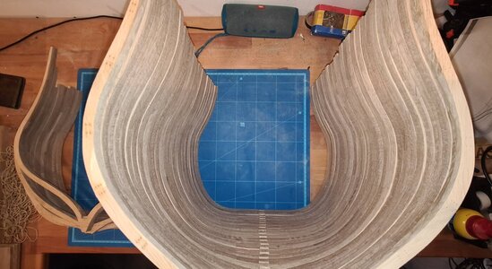
Had to saw new slats because these frames are thicker than the previous frames, otherwise the same method. Paste and cut...
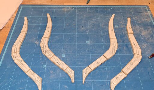
It is worth noting that only the starboard frame is included in the drawing. With a scanner, computer and printer printed a mirror image copy for port..
Then glued back together:
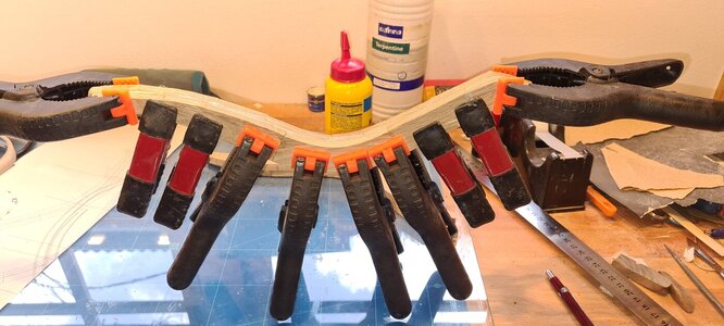
Then sanded the edges again. It is important here that it is exactly square because the bevel is measured from the edge.
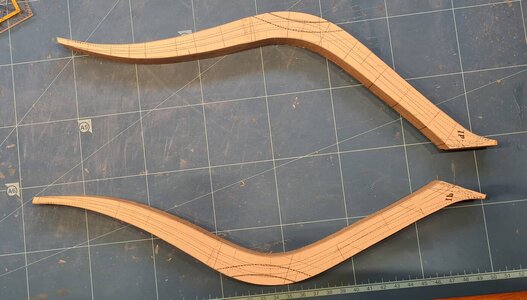
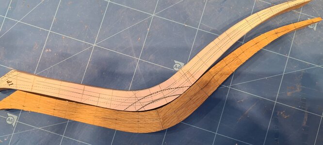
Of course I kept some margin here, because it can only be sanded into shape when the frames are placed in the bow.
Then applied the bevel...
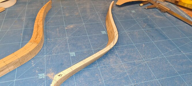
And while I'm applying the bevel I think of the following.... I should have made the frame to the right thickness first. With the other frames this was the last step and that is possible because there the bevel is very little, but here it is a lot. By first applying the bevel and then making the frame to the correct thickness, the edges of the frame move inwards and it therefore no longer has the correct hull thickness and bevel...
A Sunday afternoon wasted, another good start to this chapter.....
Anyway, do this one over again and do the port version better. The change in the method is: After gluing the two halves together, first make it to the correct thickness, taking into account that the frame tapers slightly from the outside towards the keel. What then becomes difficult is the perpendicular sanding of the edges because it should no longer be perpendicular to one side, but perpendicular to the theoretical centerline of the frame. I think the rest of the actions can be unchanged after that. Apply the bevel again after which the attachment on the keel can be shaped...
All in all a stupid mistake, should have looked more closely at the drawing..
The difference with the other frames is that they consist of two halves, are placed obliquely on the keel, do not have an equal width over the entire frame, and have a strong bevel. The combination of these makes it a lot more difficult than what I've done so far...
Below is a photo of the frames separate from the keel. I shouldn't be dissatisfied, they overlap nicely I think...

Had to saw new slats because these frames are thicker than the previous frames, otherwise the same method. Paste and cut...

It is worth noting that only the starboard frame is included in the drawing. With a scanner, computer and printer printed a mirror image copy for port..
Then glued back together:

Then sanded the edges again. It is important here that it is exactly square because the bevel is measured from the edge.


Of course I kept some margin here, because it can only be sanded into shape when the frames are placed in the bow.
Then applied the bevel...

And while I'm applying the bevel I think of the following.... I should have made the frame to the right thickness first. With the other frames this was the last step and that is possible because there the bevel is very little, but here it is a lot. By first applying the bevel and then making the frame to the correct thickness, the edges of the frame move inwards and it therefore no longer has the correct hull thickness and bevel...
A Sunday afternoon wasted, another good start to this chapter.....
Anyway, do this one over again and do the port version better. The change in the method is: After gluing the two halves together, first make it to the correct thickness, taking into account that the frame tapers slightly from the outside towards the keel. What then becomes difficult is the perpendicular sanding of the edges because it should no longer be perpendicular to one side, but perpendicular to the theoretical centerline of the frame. I think the rest of the actions can be unchanged after that. Apply the bevel again after which the attachment on the keel can be shaped...
All in all a stupid mistake, should have looked more closely at the drawing..
- Joined
- Apr 20, 2020
- Messages
- 6,241
- Points
- 738

Dear RolandMeanwhile, all frames removed from the keel, and slowly exploring the bow....
The difference with the other frames is that they consist of two halves, are placed obliquely on the keel, do not have an equal width over the entire frame, and have a strong bevel. The combination of these makes it a lot more difficult than what I've done so far...
Below is a photo of the frames separate from the keel. I shouldn't be dissatisfied, they overlap nicely I think...
View attachment 287458
Had to saw new slats because these frames are thicker than the previous frames, otherwise the same method. Paste and cut...
View attachment 287457
It is worth noting that only the starboard frame is included in the drawing. With a scanner, computer and printer printed a mirror image copy for port..
Then glued back together:
View attachment 287459
Then sanded the edges again. It is important here that it is exactly square because the bevel is measured from the edge.
View attachment 287460
View attachment 287461
Of course I kept some margin here, because it can only be sanded into shape when the frames are placed in the bow.
Then applied the bevel...
View attachment 287462
And while I'm applying the bevel I think of the following.... I should have made the frame to the right thickness first. With the other frames this was the last step and that is possible because there the bevel is very little, but here it is a lot. By first applying the bevel and then making the frame to the correct thickness, the edges of the frame move inwards and it therefore no longer has the correct hull thickness and bevel...
A Sunday afternoon wasted, another good start to this chapter.....
Anyway, do this one over again and do the port version better. The change in the method is: After gluing the two halves together, first make it to the correct thickness, taking into account that the frame tapers slightly from the outside towards the keel. What then becomes difficult is the perpendicular sanding of the edges because it should no longer be perpendicular to one side, but perpendicular to the theoretical centerline of the frame. I think the rest of the actions can be unchanged after that. Apply the bevel again after which the attachment on the keel can be shaped...
All in all a stupid mistake, should have looked more closely at the drawing..
I admire the dedication and the precision you apply in building this beautiful model!!
there is no doubt that these qualities will bring you beautiful and impressive achievements, well done friend.


Learning by doing - in moment you are realizing some mistakes you are getting angry, but this mistake you will never do once more in your life.
So the sunday afternoon was not wasted time - this is called "experience" -> good work my friend
and the next will be easier
So the sunday afternoon was not wasted time - this is called "experience" -> good work my friend
and the next will be easier
Not quite finished the first frames yet, but I run into a 'problem', namely that I don't understand the drawing. This has happened many times before that I thought the drawing was wrong, but until now it was always just me. It will probably be the same this time....
Before I explain what this problem is, let me tell you where I am..
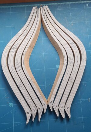
Here are all 8 half frames, d1 t/m d4 port and starboard... In the meantime they have also been sanded into shape like d1. The only thing that hasn't been done here yet is finishing them on the keel. This is a somewhat more complex shape with a bulge that falls into the frame where d4 is mounted at an angle of 88 degrees, d3 in 86, d2 in 84 and d1 in 82 degrees relative to the keel. This can also be seen in the drawings that are still on the frames above. See drawing below...
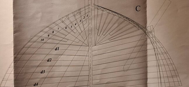
d1 to d4 are not equally thick everywhere. They become slightly narrower towards the keel. I did this with a thicknesser where I made a tool from two sheets of mdf that I can lift on one side so that the top is not exactly parallel to the bottom but at an angle. I glued the frame on this with double-sided tape and then lightly milled the whole thing in the thicknesser.
When I started finishing the frames on the keel I discovered that I first had to finish the rabit here (where the skin planks fall against), see photos...
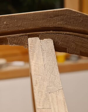
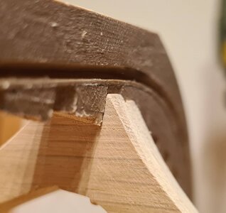
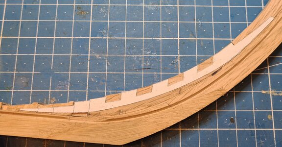
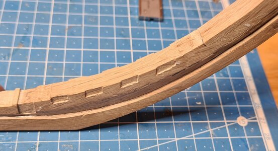
I made this according to the drawings below...
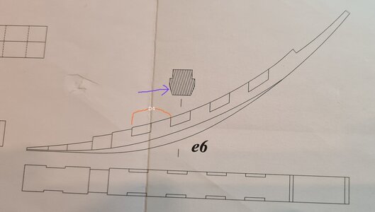
I have indicated here where the frame d4 will end up. You can clearly see that the lower part is chamfered towards the rabit...
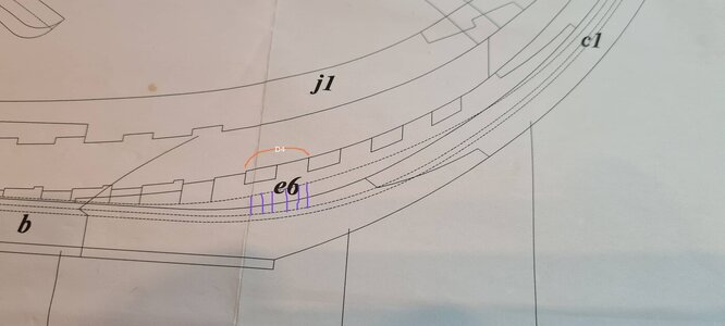
With purple I have indicated which part should be chamfered.
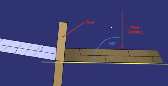
And then comes my mystery.... Is the drawing wrong or am I not seeing it right?
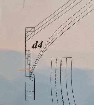
This drawing shows the keel and frame d4. What I see here is a straight line all the way from the top of the keel to the rabit. According to this drawing, there is no chamfered part as indicated in the drawing above. According to this drawing I have to narrow the keel above the rabit in its entirety.... Am I doing something wrong or is this indeed an error in the drawing? (would be the first...)
Before I explain what this problem is, let me tell you where I am..

Here are all 8 half frames, d1 t/m d4 port and starboard... In the meantime they have also been sanded into shape like d1. The only thing that hasn't been done here yet is finishing them on the keel. This is a somewhat more complex shape with a bulge that falls into the frame where d4 is mounted at an angle of 88 degrees, d3 in 86, d2 in 84 and d1 in 82 degrees relative to the keel. This can also be seen in the drawings that are still on the frames above. See drawing below...

d1 to d4 are not equally thick everywhere. They become slightly narrower towards the keel. I did this with a thicknesser where I made a tool from two sheets of mdf that I can lift on one side so that the top is not exactly parallel to the bottom but at an angle. I glued the frame on this with double-sided tape and then lightly milled the whole thing in the thicknesser.
When I started finishing the frames on the keel I discovered that I first had to finish the rabit here (where the skin planks fall against), see photos...


I made this according to the drawings below...

I have indicated here where the frame d4 will end up. You can clearly see that the lower part is chamfered towards the rabit...

With purple I have indicated which part should be chamfered.
And then comes my mystery.... Is the drawing wrong or am I not seeing it right?

This drawing shows the keel and frame d4. What I see here is a straight line all the way from the top of the keel to the rabit. According to this drawing, there is no chamfered part as indicated in the drawing above. According to this drawing I have to narrow the keel above the rabit in its entirety.... Am I doing something wrong or is this indeed an error in the drawing? (would be the first...)
Hello Roland, I think that the last picture can cause some confusion. It's just a guess because I don't know the plan, but you'll need the slope to be able to plan properly. So I believe that the way you prepared it is correct. It is just a guess.
Hi Roland
Looking at how your frame lines up with the rabbet all that is required is to fair the keel so that the profile of the frame runs to the bottom of the rabbet.I would do this AFTER the frames are fitted.This is how I did it on Saint Philippe using one of the small Proxxon self sanding adhesive sanding pads in my rotary tool then hand sanding.I think you are trying to accomplish too much putting this chamfer on before the framing is together, you are boxing yourself into a corner
Kind Regards
Nigel
- Joined
- Aug 8, 2019
- Messages
- 5,568
- Points
- 738

Here is how @Michele Padoan build it.
Post in thread 'LE COMMERCE DE MARSEILLE SCALA 1/72' https://shipsofscale.com/sosforums/threads/le-commerce-de-marseille-scala-1-72.3667/post-78551
Maybe he can tell you? There is this forum for.
Post in thread 'LE COMMERCE DE MARSEILLE SCALA 1/72' https://shipsofscale.com/sosforums/threads/le-commerce-de-marseille-scala-1-72.3667/post-78551
Maybe he can tell you? There is this forum for.
I think this view is "normal" to the surface of the frame to get a the real view of him. Otherwise its impossible to build him. I created the same view for my Redoutable. If you look to D1 you will check that there is a bigger gap to the keel. This is because the bigger angle from the cantframe D1 to the keel. Everything´s allright.
Last edited:
Thank you all for the help! I really appreciate it you take the time to answer my question, I believe I know what to do….
My conclusion is: there is a discrepancy in the drawings. What I will do is narrowing the keel above the rabbit so that is in sync with the drawing of the frames…. I believe this is easier, creates a nicer result, is more solid and I believe is also what @Michele Padoan has done if I look at his photos…
My conclusion is: there is a discrepancy in the drawings. What I will do is narrowing the keel above the rabbit so that is in sync with the drawing of the frames…. I believe this is easier, creates a nicer result, is more solid and I believe is also what @Michele Padoan has done if I look at his photos…
Last edited:


