• LUCZORAMA SHIPWRECK SCAVENGER HUNT GIVEAWAY. 4 Weeks of Fun • 1 Legendary Prize ((OcCre’s Fram Ship)) • Global Crew Welcome!
    **VIEW THREAD HERE**

Bomb Ketch Salamandre 1:48

!"Sliding Sled Saw Slays Slots"!
I bet this took a fraction of the time that it would have took milling each slot. Unfortunately, on my L'Invention the frames fit into small notches cut into each side of the keel structure so I'm going to need to mill and/or chisel my way through that aspect. Right now I envy the way your project is going together!

Looks like you may have eaten / drank up the sliding table savings :) Happy 4th!
 
This may help shipyards that have a small table-saw, but no milling machine:

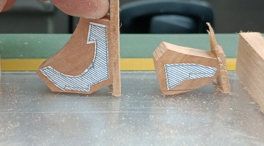
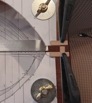
1. Workers cut and brace the piece, so the desired face is parallel to the table:

20250707_153158.jpg

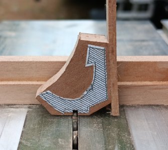
2. Workers then adjust the blade height to the correct depth:
20250707_153732.jpg

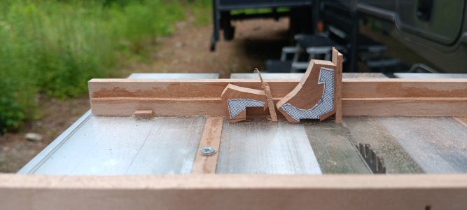
3. Finally, after multiple passes a smooth flat face is created:
20250707_154822.jpg

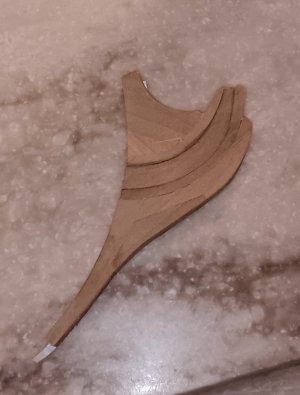
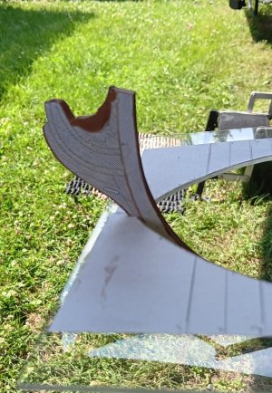
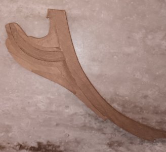
Using the Proxxon and sliding table as a "milling machine", workers were able to fabricate and glue up the Knee of the Head:
20250707_234901.jpg
 
This may help shipyards that have a small table-saw, but no milling machine:

1. Workers cut and brace the piece, so the desired face is parallel to the table:

View attachment 530670

2. Workers then adjust the blade height to the correct depth:
View attachment 530671

3. Finally, after multiple passes a smooth flat face is created:
View attachment 530669

Using the Proxxon and sliding table as a "milling machine", workers were able to fabricate and glue up the Knee of the Head:
View attachment 530672
You give hope to FET owners everywhere!

My question for the yard boss is what method did the workers use to ensue the face to be milled was parallel to the table?
 
You give hope to FET owners everywhere!

My question for the yard boss is what method did the workers use to ensue the face to be milled was parallel to the table?
I have several thin (1-2mm) planks that I stack on top of the piece parallel to the cut line.

The opposite edge of these pieces are then lined up with the blade slot in the sliding table.

Rudimentary but effective...
 
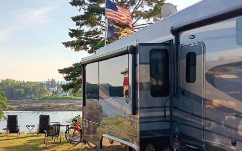
5 days on the beautiful shoreline of Acadia National Park, Maine (last photo).

Workers completed the baseplate from which the keel and frames will rise!!!

The baseplate is 0.10" thick plexiglass, laid on a stiff wooden frame.

Two strips of 3/4"W x 1/8"H aluminum will sandwich the keel in place.

Workers also laid out and labeled the centerline of each frame.

Keel jig.jpg20250711_225226.jpg

Last day for workers to enjoy the ocean:(:(:(! Tomorrow, the shipyard moves to inland Maine and then crosses the border into Canada next week.

Bar Harbor.jpg
 
La Salamandre workers (Toulon, FR) are feeling right at home. Yesterday, the shipyard passed into French Speaking Quebec, Canada.

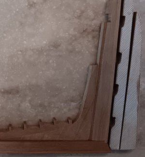
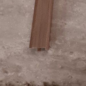
The last several days were spent making the stern rising wood, with a complicated curved scarf joint (photo 1) and a very small mortise/tenon joint on the sternpost (photo 2).

The sternpost assembly is glued, as well as the curved scarf joint. Neither are glued to the keel yet.

Tomorrow shipyard will move to the shores of the St Lawrence River in Montreal for four days of sightseeing and a maybe a bit of shipbuilding!

afat deadwood.jpg20250715_185224.jpg
 
Kurt,
We do get a mouse in our traps once in a while, but they don't help with the build!

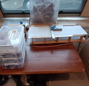
Below are pics of the workspace and view out the workshop window.

Good thing with a TINY workshop....it HAS to stay neat and organized, unlilke the shop at home ROTF ROTF
View attachment 531433View attachment 531434
What a pleasure Brad. Having a forever changing view from your shipyard - stunning. Cheers Grant
 
The Montreal shipyard reached two major milestones:

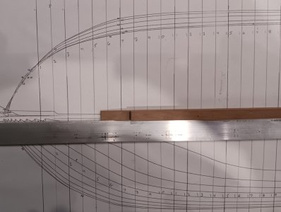
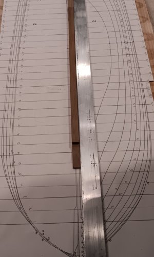
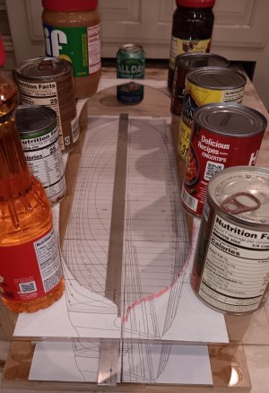
1. The building jig was completed:

20250717_161108.jpg

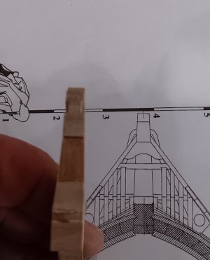
Unfortunately, I made the jig too short. The below photo shows the slot in the bow DID NOT take into account Knee of the Head (it was only cut to stem):
20250717_150206.jpg
To fix this, the jig slot had to be extended (see photo below). Now the Knee of the Head and length of the keel dry fit precisely with the plans!!!
20250718_202729.jpg

2. The Knee of the Head was completed and tapered to the profile in the plans
20250718_115308.jpg20250718_095705.jpg

Workers had a wonderful day bike riding through the Old City of Montreal:
20250718_150659.jpg20250718_142330.jpg20250718_142200.jpg20250718_134019.jpg20250718_125606.jpg

The "La Salamandre" Keel will be laid tomorrow. How fitting this will be done in a French speaking province of Canada.
 
$3 sliding cross-cut table for Proxxon table saw.

I have no milling machine to cut frame slots in the keel.

Shipyard workers quickly realized the Proxxon table saw needs a sliding cross-cut table!!

The provided attachments are not capable of cutting these slots to the required accuracy. This is the "foundation" of the entire model, so accuracy is crucial!!

SO...off to the ACE hardware store in tiny Belfast, Maine, to build one for under $3!

Below are the parts purchased (Less than $3 for the screws):
2ft of scrap hardwood (1.5" x 0.25"). (Free from shipyard scrap pile)
8 x M3 countersink machine screws (Length 12mm / thread diameter 3mm)
6 x M3 countersink machine screws (Length 6mm / thread diameter 3mm)
0.1 inch thick plexiglass 5" x 10" (ACE gave me a 12" x 5" piece from a broken slab for free)

Steps with photos:

1. Cut two strips 0.464" wide x 0.172" thick x 10" long)
2. Cut two strips (0.300" wide x 0.15" thick x 10" long)
3. Slide the wider strip into the travel groove
4. Using instant glue, set the narrower strip on top, apply pressure.
NOTE: continue to move the two pieces back and forth in the groove for two minutes while applying pressure. This will ensure none of the instant glue bonds to the metal of the table saw guides.
5. Pull them from the slots and use a file to remove and glue that may have leaked from the joint.
6. Ensure they slide freely, without binding. If they bind, find the "high" spots and file or sand till they slide smoothly.
Result:
View attachment 529848

1. Cut the 0.1" plexiglass to 5" x 10". If you have enough cut to 10" x 10" (I didn't).
2. Place the wood runners in the slots. Place 3 strips of paper under the runners, so they stand "slightly proud" of the table.
3. Run instant glue along the top of the runner and press on the plexiglass squarely for two minutes.
SAME NOTE: continue to slide the cross-cut table so no glue can bind to the metal
4. Slide back and forth until it slides freely (file or sand if necessary...mine slid freely at this point).
View attachment 529825

1. Pre-drill three holes on each guide, using a 3/32 drill bit for the machine screws. I went all the way through (then sanded the bottom).
2. Use a 15/64" drill bit to make the countersink hole for the screw heads.
3. Insert the 3 screws (use 5 if your plexiglass is 10" x 10").
4. Result should look like this
View attachment 529826

1. Cut two pieces (0.25" x 0.65" x 10") for the bottom "wood rest" and "top brace"
2. Using jigs/stops/clamps/etc, PRACTICE setting the bottom "wood rest" EXACTLY PERPENDICULAR (you only get one chance).
3. Use instant glue to set the bottom "wood rest"
4. Use instant glue to set the "top brace". This is not critical to make exactly perpendicular.
5. Use the eight 12mm M3 screws to reinforce these glued joints. Ensure these are countersunk, so they do not drag/scrape your table.
See below:
View attachment 529827

1. Run the sliding cross-cut table through a blade raised 0.50" (I felt this was adequate for 1/4" ship modeling). This will give you 0.40", available for cross-cuts.
2. Do a test and experiment with blade height adjustments/lock stops/etc
3. You are now ready to begin cutting accurate and repeatable frame slots in your keel.
View attachment 529828

Shipyard will start milling the frame slots in the keel soon!
I couldn’t put off following in your footsteps and started building a crosscut sled using your post as a guide. Instead of wood runners, I had a piece of 1” x .25” aluminum bar in the stash from which I could mill the runners on the FET. I made a sled for a full-size saw when I was in RI, but was never happy with the hardwood runners, so I have eschewed those. I plan to do a taller fence than yours so I can use more blade, but thank you for your awesome tutorial!
 
Last edited:
,I couldn’t put off following in your footsteps and started building a crosscut sled using your post as a guide. Instead of wood runners, I had a piece of 1” x .25” aluminum bar in the stash from which I could mill the runners on the FET. I made a sled for a full-size saw when I was in RI, but was never happy with the hardwood runners, so I have eschewed those. I plan to do a taller fence than yours so I can use more blade, but thank you for your awesome tutorial!
Glad it was helpful.

Doing the taller fence at the outset is smart.

I'm sure there will come a time when I need to use more of the blade.

The hardwood runners have worked well, no binding. Most likely because I rubbed them well with wax (sort of a sealer/lubricant, all in one).
 
Glad it was helpful.

Doing the taller fence at the outset is smart.

I'm sure there will come a time when I need to use more of the blade.

The hardwood runners have worked well, no binding. Most likely because I rubbed them well with wax (sort of a sealer/lubricant, all in one).
Seasonal humidity changes were my main frustration. Either sled was sloppy or tight enough to bind. The runners for a mini-sled on a FET are probably small enough that it shouldn't make a difference.
 
Dividing 0.37 by 42 frames equates to an average of 0.0088inches thicker in the keel area of each frame (about the thickness of two pages of copy paper).

SHIPYARD SOLUTION: Shipyard Superintendent will direct workers to sand each frame around the keel area more. The Superintendent will personally measure the thickness of EACH frame until BOTH the TOP and BOTTOM measure equally at 0.386".
These are the calculated details I love the most, Brad. :) Looking with interest to the outcome.
Regards, Peter
 
Back
Top